


4
www.atlona.com
Toll free: 1-877-536-3976
Local: 1-408-962-0515
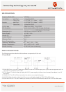
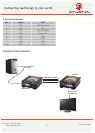
2. Rear Panel
1. POWER/DDC: Connect the DDC output of the transmitter to the DDC input of the receiver unit using CAT5/6/7 cables.
2. VIDEO 2: Connect the VIDEO 2 output of the transmitter to the VIDEO 2 input of the receiver unit using CAT5/6/7
cables.
3. VIDEO 1: Connect the VIDEO 1 output of the transmitter to the VIDEO 1 input of the receiver unit using CAT5/6/7
cables.
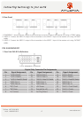
1. Dual Link DVI-D Pin Definition
DVI-D Receptacle Connector
Digital-Only Connector Pin Assignments
Pin Signal Assignment Pin Signal Assignment Pin Signal Assignment
1 T.M.D.S Data2- 9 T.M.D.S Data1- 17 T.M.D.S Data0-
2 T.M.D.S Data2+ 10 T.M.D.S Data1+ 18 T.M.D.S Data0+
3 T.M.D.S. Data2/4 Shield 11 T.M.D.S. Data1/3 Shield 19 T.M.D.S. Data0/5 Shield
4 TMDS Data 4- 12 TMDS Data 3- 20 TMDS Data 5-
5 TMDS Data 4+ 13 TMDS Data 3+ 21 TMDS Data 5+
6 DDC Clock 14 +5V Power 22 T.M.D.S. Clock Shield
7 DDC Data 15 Ground (for +5) 23 T.M.D.S. Clock+
8 No Connect 16 Hot Plug Detect 24 T.M.D.S. Clock-
PIN ASSIGNMENT