


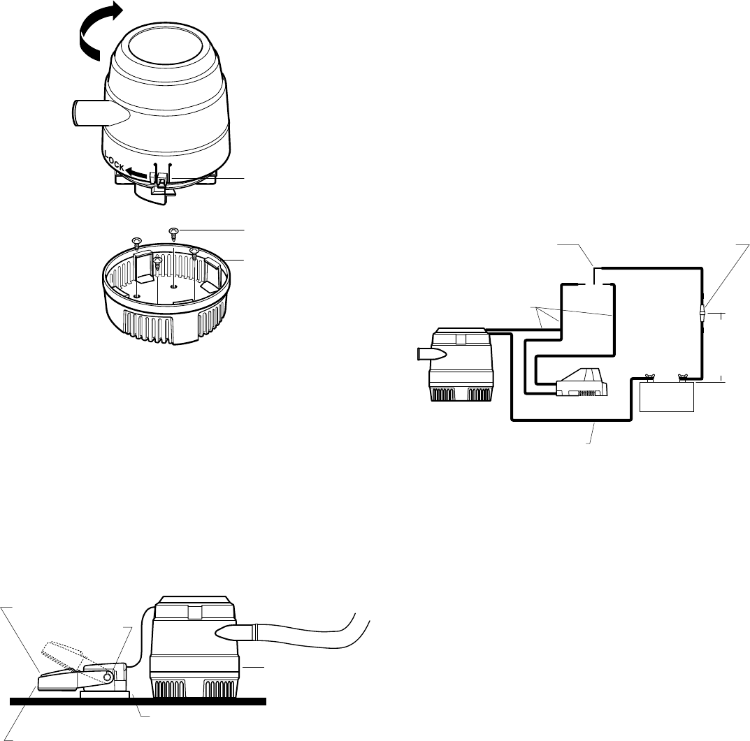
12 Volt Battery
–
+
Black Wire
Automatic Float Switch
Brown Wire
Off
AutoManual
3-Way Switch On/Auto/Manual
HD 1700: 10 Amp Rating
HD 2000: 12 Amp Rating
HD 1700: 10 Amp Fuse
HD 2000: 12 Amp Fuse
•
•
•
•
•
•
•
72" (183mm)
Maximum
Length From (+)
Terminal To
Fuse Holder
•
•
• •
•
•
1. Choose a bilge pump mounting location in the lowest accessible part of the
bilge. In this location, pump will remove the last 1" (2.54 cm) of standing
water. Also, pump should be as close to the thru-hull connector as
possible, for short discharge hose length.
2. To install mounting pad on fiberglass hull:
Sand gelcoat or paint off the mounting surface to create an area that is 3"
(7.6cm) wider than the mounting pad on each side.
Completely cover the mounting pad with fiberglass. Saturate the fiberglass
with resin, and press the fiberglass edges down against the hull to adhere
the pad in place. Roll out the fiberglass to remove any uneven surfaces, air
bubbles, or excess resin.
To install mounting pad on aluminum hull:
If your boat is not equipped with a bilge pump mounting pad we recom-
mend that you consult your boat dealer or repair facility for instructions
regarding fabrication and installation of a suitable mounting pad.
PUMP MOUNTING INSTRUCTIONS
NOTE: The selected float switch must have an amp rating equal to or greater
than the recommended fuse.
Make all wire connections above the highest possible water level, using
marine grade wire connectors only. Waterproof all connections with suitable
materials.
NOTE: Failure to make waterproof connections and fuse pump
properly will void the product warranty.
1. Splice suitable lengths of brown and black 16-gauge wire to existing pump
wiring, enough to reach ON/OFF/AUTO switch, automatic float switch, and
battery.
2. Using insulated terminal connectors:
Connect positive lead (brown) to the ON/OFF/AUTO switch.
Connect negative lead (black) to negative (-) battery terminal.
In a location easily accessible for changing fuses, splice fuse holder into
positive lead (brown). The fuse holder must be installed within 72" (183 cm)
of the positive (+) battery terminal. Connect remaining lead from fuse
holder to positive (+) terminal of the three-way switch.
3. Splice the remaining positive lead (brown) from the automatic float switch
into the positive lead (brown) from the pump.
1. Select a location on the pump mounting pad
forward
of the bilge pump.
NOTE: It is important to locate the switch
forward
of the pump to minimize
the possibility of running the pump when there is not enough standing
water, causing the pump to draw air and not turn off.
2. Attach shim to mounting pad with a layer of polyester resin.
3. After resin has dried, center automatic float switch on top of shim.
If you have an Attwood switch
without
a cover, thread two #8 screws
through attachment holes on switch. Fasten securely into mounting pad.
If you have an Attwood switch
with
a cover, thread three #8 screws through
cover, then switch. Fasten securely to mounting pad.
HOSE CONNECTION INSTRUCTIONS
1. If no thru-hull connector exists:
Install connector well above the water line (just under the rub rail is best) on
the driver side, where water discharge can be easily monitored. Drill a hole
through the hull to clear the connector threads.
Apply marine sealant around inside of nut flange (do not allow sealant to
contact pump housing). Fully insert thru-hull connector, and screw nut
flange down firmly. Do not over tighten.
2. Run hose from pump nozzle up to thru-hull connector, through the most
direct and unobstructed path possible.
3. Before connecting hoses, cut any extra length from hose that causes
downward dips or kinks in discharge line (dips can trap water and airlock
the pump). Be sure the hose tension on the pump outlet is minimized to
reduce stress on the pump components.
4. Place hose clamps onto hose ends. Connect ends to pump nozzle and
thru-hull connector, ensuring that hose ends fit tightly over barbs.
5. Secure both connections with hose clamps.
WIRING INSTRUCTIONS FOR AUTOMATIC OPERATION
1. Determine which direction you want pump outlet fitting to point after
installation. Mark pump base and mounting pad in desired position.
If
Automatic Float Switch is to be installed, allow enough room on pad for
shim and switch.
2. Remove pump base from motor housing by depressing lock button and
twisting clockwise.
3. Align base with pad at marks, and fasten with four #8 screws.
4. Attach pump to base by aligning four retaining tabs and twisting counter-
clockwise until the lock button snaps into place.
AUTOMATIC FLOAT SWITCH INSTALLATION
Figure 2
Retaining Tabs
LOCK
•
Mounting Screws
Locking Button
•
•
Figure 3
Bilge Pump
Automatic Float Switch
•
•
•
Float Switch Must Shut Pump Off Before
the Pump Cavitates (Draws Air and Stops Pumping)
•
Shim
Test Knob
•
Figure 4