


AXIS Electrical Safety Kit A/B Page 7
ENGLISH
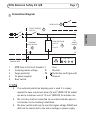
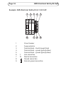
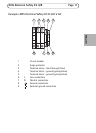
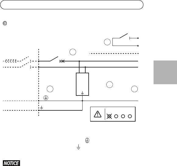
Connection Diagram
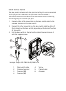
• If an external protective bonding wire is used it is recom-
mended to have a miminum area of 6 mm
2
(AWG 10) for indoor
use and a minimum area of 10 mm
2
(AWG 8) for outdoor use.
• The circuitry shall be connected to an external double pole cir-
cuit breaker in the building installation.
• The door switch shall only be used for signal voltage (SELV) and
shall not be connected to the mains voltage or power supply.
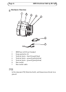
1 MCB fuse 4 A (circuit breaker) L Line
2 Incoming mains voltage N Neutral
3 Surge protector PE Protective earth (ground)
4 To power supplies Ground
5 Door switch
CIRCUIT BREAKER/
FUSE 4 A
DOOR SWITCH
EXTERNAL PROTECTIVE
BONDING WIRE
L
N
L
1
N
1
N
PE PE
1
L
SURGE PROTECTOR
230 V AC
or
120 V AC
TO
POWER
SUPPLIES
INCOMING
MAINS VOLTAGE
TT - TNS - TNC - IT
1
5
3
2 4