13
Optional Remote Installation
Optional Installation of Deluxe Remote
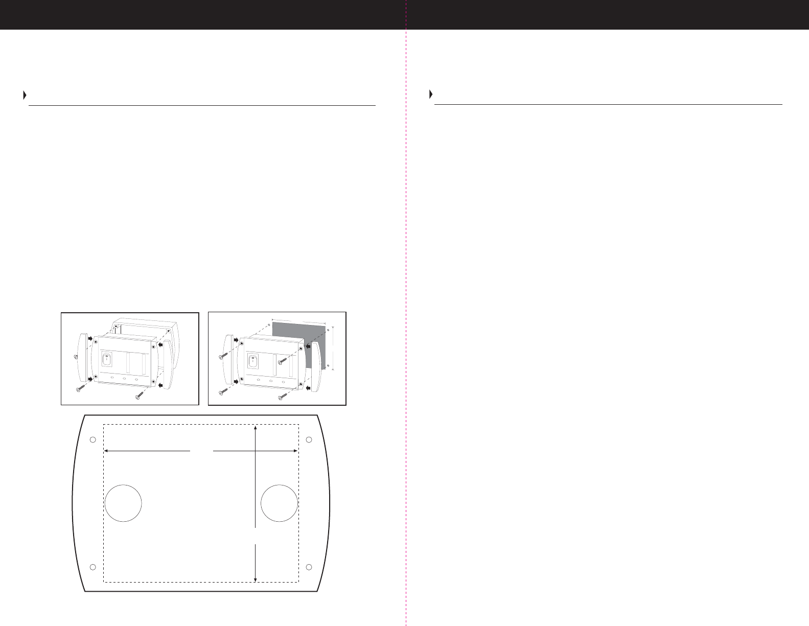
Step 3 - Use photocopy of the drill template below to mark (4) mounting holes and (2)
cable thru holes. See illustration No. 1 for surface mount application.
- or -
Use drill template to mark and cut a 2-5/8" x 2-1/8" opening and (4) mounting holes.
See illustration No. 2 for flush mount application.
Note: Use caution prior to drilling or cutting to ensure proper clearance from
existing wiring and hardware.
Step 4- Assemble remote panel without snap on mounting covers. Place cable in socket
on the back of remote and then thru the holes, align mounting holes and using a hand
screwdriver, install the 4 stainless steel screws provided. Snap on mounting ear covers
to complete installation.
Step 5- Run the remote cable, to the inverter- be careful of sharp objects.
Step 6- Plug the remote cable into the socket found on the previously installed backing
plate. Your remote is now ready for use.
6
Installation Guidelines
Mounting your Inverter Continued
Fuses: As stated in this manual, for an ABYC E-11 compliant installation, this Inverter
must be installed with an inline fuse in the positive (+) cable on the DC side of the
inverter (between the battery and the inverter) at a distance of seven inches from the
battery connection (Please see Specifications Table in this Manual for correct sizing).
If this external fuse blows, or if the breaker trips on the larger models, there is a short
or overload in the DC wiring. Find and fix the problem before replacing the fuses or
resetting the breaker. After replacing the fuse, reconnect the inverter.
The 2000 to 3000 watt True Power inverters are equipped with a magnetic breaker for
the hardwired connection and a thermal breaker for the additional GFCI outlet on the
unit. Again, all units should be serviced only by a professional qualified electrician, or
more preferably by our factory service department. For any service issues, please call
toll free 1-800- 824-0524.
To Mount the TruePower Inverter:
1. Turn the On/Off switch on the front panel of the inverter to Off position.
2. Select an appropriate mounting location and orientation.
3. Hold the inverter against the mounting surface, mark the position of the mounting
screws, and then remove the inverter.
4. Drill pilot holes for the four mounting fasteners ( Use caution prior to drilling or cutting
to ensure proper clearance from existing wiring and hardware).
5. Fasten the inverter to the mounting surface with four hardware fasteners.
Note: For the best load starting performance, the DC cables should be short and
large as possible. A solid, low resistance connection to the DC power source is
important for proper operation of the TruePower Inverter. Using a smaller cable may
cause the inverter to shut down under a heavy load.
Note: A ground stud can be found on the rear panel of the TruePower inverter as illustrated
in “TruePower Overview” earlier in this manual. The ground stud must be connected to
a grounding point, which will vary depending on where the TruePower inverter is installed.
We recommend an #8 gauge AWG or larger copper wire. In a vehicle, please secure a
ground wire from this stud to the chassis of your vehicle, keeping the distance of the
ground as short as possible. In a boat, connect to the boat’s grounding system. In a fixed
location connect the inverter’s ground stud to earth by connecting to a ground rod (a metal
rod pounded into the earth) or other proper service entrance ground.
Drill Template
2-1/8
2-5/8
cut along line for flush mounting
No.1 Surface Mount Installation
No. 2 Flush Mount Installation
2-5/8
2-1/8
Power Over TempOver Load
On
Off
0
100
%
100
%
0
DC
Input Voltage
Inverter
Output Current
On Board
Solutions
A ProM
ariner Com
pa
ny
Deluxe Inverter Remote
Power Over TempOver Load
O
n
Off
0
100
%
100
%
0
DC
Input Voltage
Inverter
Output Current
On Board
Solut ions
A ProMariner Company
Deluxe Inverter Remote


