


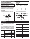
Wire Size Cranking Rating
9.75 sec. (10 repeats)*
Intermittent Rating
5 min. (UL 1107)
Continuous Rating
(UL 1107)
1/0 450A 375A 250A
2/0 500A 450A 300A
2x2/0 800A 600A 450A
* Blue Sea Systems Engine Starting Standard
Marine Electrical Prod
ucts
L-Series ACR with Coil Economizer
Blue Sea Systems Inc. Phone (360) 738-8230
425 Sequoia Drive Fax (360) 734-4195
Bellingham, WA 98226 USA E-mail conductor@bluesea.com
www.bluesea.com
Guarantee
Any Blue Sea Systems product with which a customer is not satisfi ed may
be returned for a refund or replacement at any time.
6693 Rev.005
Installation Instructions
PN 9112
Features
• Automatically combines battery banks during the charging cycle and
isolates under discharge
• Override for emergency engine paralleling to start an engine
• Activates whether the charging source is an alternator or battery charger
• Output for “ON” indication LED
• Integrated coil control minimizes heating and amperage draw
• Hermetically sealed contacts/vaporproof
• Single or double sensing
• Pulse circuit requires very low current draw when contact is closed
• Ignition protected - Safe for installation aboard gasoline powered boats
• Meets SAE J1171 - External ignition protection requirements
• UL Recognized - UL 508 industrial control equipment
Mounting
• Select a dry and protected mounting location near the battery banks or the
battery switch.
• Choose a cool, dry, and well-ventilated location if possible. The L-Series ACR
with Coil Economizer may become very warm when operating at full
current-carrying capacity.
• Avoid locations directly above batteries where corrosive fumes may be present.
• Mount the relay securely with #10, #12, or 5mm screws through the fl anges at
the base. Hole size is 0.22 inches.
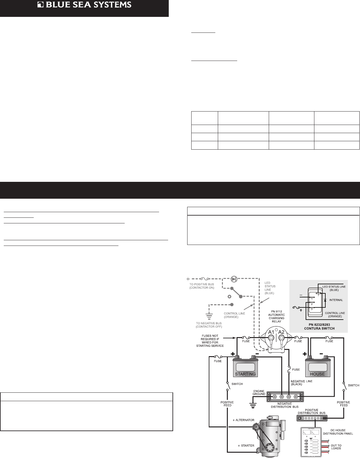
Electrical Connections
The wiring confi guration to the right represents a common installation and is not
meant to be a guide for the wiring of a specifi c vessel. Consult your marine
electrical professional for the wiring system applicable to your boat.
Disconnect the positive battery connection before beginning the installation. If
there is a possibility of tools causing a short, disconnect the negative terminals
before disconnecting the positive battery terminals.
Make electrical connections based on the wiring diagram to the right. Consult the
Wire Sizing Chart on the following page to determine the appropriate wire size.
If a manual control is installed to use this device for emergency paralleling of
batteries for engine starting, no fusing is required in the main circuit, but wire
sizes should be chosen for the full starting currents. If starting service is not
included, choose circuit protection according to wire capacity. If a charging
source is present and the relay is closed in automatic mode when an engine is
started, starting currents can fl ow through this circuit. This can result in blowing of
protection fuses if the wiring system does not limit the current.
Voltage Sensing
The 9112 ACR is designed to sense, and operate from, the voltage supplied by
either battery. In a typical application, the engine driven alternator is connected to
the starting battery. When the starting battery is suffi ciently charged, the ACR will
close and share charging with the house battery. If a shore charger is supplying
the house battery, when it has brought the house battery up to voltage, the ACR
will close and share with the starting battery.
Typical Confi guration - Sense Both Battery Banks
• Connect one battery bank to stud terminal A1
• Connect the other battery bank to stud terminal A2.
• Connect the black line (negative) from the relay to the battery negative
through a 10-15 Amp in-line fuse to prevent fault current from fl owing in
this wire.
Caution: Battery cable terminals must be placed at the bottom of the stack
under the sensing wire terminals, the fl at washer, the lock washer, and the nut.
Tighten securely. Refer to the Lug Installation Diagram on following page.
Specifi cations
Combine 13.6, 27.2 Volts
Automatic Drop Out 12.6, 25.2 Volts
Automatic Over Voltage Drop Out 15, 30 Volts
Combine Time Delay 30 Seconds
Coil Circuit:
Input Voltage: 9 - 36 Volts DC
Power Consumption: Inrush, 130ms: 3.8 Amperes@12-36V DC
Holding 12 Volts: 0.13 Amperes@12V DC
0.07 Amperes@24V DC
Main Power Contacts:
Voltage Rating 60 Volts DC
Stud Terminal Size M8 (accepts 5/16” terminals)
Terminal Stud Torque 80-100 In-lb
Contact Form SPST-NO
Inrush Rating: 250ms (10 repeats)* 2000 Amperes
Mechanical Life 1 Million Cycles
Make Current@10,000 Cycles: 2000 Amperes@28V
Break Current@10,000 Cycles: 2000 Amperes@28V
Sense One Battery Bank
• Remove red ring terminal voltage sensing wire from the stud terminal A1or A2
associated with the battery bank that you don’t want to sense.
• Place the removed ring terminal over the stud terminal to which the other
voltage sensing wire is attached, or insulate the ring terminal and fold it out
of the way.
The negative (black wire) connection from the relay to the battery negative must
be as short as possible. Because the built in coil economizer causes current
pulses in the control circuit, there may be noise present on the black wire and it
should not be run with sensitive wires from other circuits.
Wiring Diagram
• Gray dashed lines indicate optional connections