


Installation Instructions (continued)
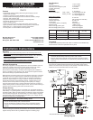
Wiring Identifi cation
Lug Installation Diagram
Manually Connect and Disconnect Battery Banks
A control switch such as a Blue Sea System’s Switch Panel 8270 or Contura Switch
8232/8283 may be used to manually connect and disconnect battery banks by
overriding the L-Series ACR voltage sensing circuit.
To connect a manual override switch:
• Connect Control Line (orange) to the center common terminal of an
ON-OFF-ON single pole, double throw switch.
• Connect negative and positive to the outside terminals of the switch.
• When the control line is switched to a positive supply, the relay is closed when
ever the voltage is greater than about 9 volts at either terminal.
• When the control line is switched to the negative supply line, the relay will be
held open.
• When the switch is in the center position, with no command to the relay, the
relay will operate automatically to close and open when it senses charging
voltages. The control signal passes very little current and can be supplied from
any fused positive source.
Remote Indicator Lamp
To determine at a remote location when the battery banks are connected, a remote
LED indicator can be connected to the L-Series ACR. Suitable indicator lamps are
Blue Sea Systems PN 8033 (amber), PN 8171 (red), or PN 8172 (green).
To connect an LED indicator:
• Connect the red wire of the LED to a positive source.
• Connect the yellow wire of the LED to the Status Line (blue).
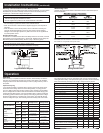
Wire Sizing Chart
Use the wire sizing chart below to determine minimum wire sizes open to
free air circulation.
60.0
80.0
120.0
160.0
210.0
245.0
285.0
330.0
385.0
445.0
51.0
68.0
102.0
136.0
178.5
208.3
242.3
280.5
327.3
378.3
1
0
00
000
0000
2
4
6
8
10
Note: For wire with 105°C insulation rating, no more than 2 conductors
are bundled, and not enclosed in conduit or other extra insulation.
Not suitable for sizing flexible shore power cords.
Performance Specifi cations Units Min Nom Max
AUTOMATIC MODE@25C
Pickup Voltage (PU1) V DC 13.5 13.6 13.7
Drop-out Voltage (DO1) V DC 12.5 12.6 12.7
Over Voltage (OV1) V DC 14.8 15 15.2
Pickup Voltage (PU2) V DC 27.0 27.2 27.4
Drop-out Voltage (DO2) V DC 25.0 25.2 25.4
Over Voltage (OV2) V DC 29.6 30 30.4
Over Voltage Hysteresis V DC .35
Coil
Inrush Current A 1.5 2.8 3.5
Inrush Time s .80 .100 0.13
Hold Current, Ave A .03 .110 .160
PWM Frequency kHz 20
Time Delay on Close s 25 30 35
MANUAL MODE
Maximum Input Voltage V DC - - 36
Pickup Voltage V DC 8 8.5 9
Drop-out Voltage V DC 6 6.5 7
Current Draw When Contactor is “Off” mA .05 1 2
Status Line
(Open Collector with 1k Limiting Resistor)
Voltage, Maximum V DC - - 36
Current, Maximum mA - - 36
Operation
Control
Line
PN 9112
Contacts
Starting Battery
Voltage Sense
House Battery
Voltage Sense
Relay ON (Manual)
>9V Closed >9 Anything
>9V Closed Anything >9
Relay Pickup
(Auto)
Conditions to turn
relay on
Open Open
<13.6,
15 to 27.2,>30
<13.6,
15 to 27.2,>30
Open Closed
13.6 to 15,
27.2 to 30
<Starting Battery
Open Closed < House Battery
13.6 to 15,
27.2 to 30
Relay Dropout
(Auto)
Conditions to turn
relay off
Open Closed
12.6 to 15,
25.2 to 30
12.6 to 15,
25.2 to 30
Open Open
<12.6,
15 to 25.2, >30
<12.6,
15 to 25.2, >30
Relay Off (Manual) <1V Open Anything Anything
Anything Open <6 <6
Table of Operation
Operation
When all wiring is complete and has been checked, restore battery connections.
The relay may momentarily energize when power is fi rst applied. The automatic
charging circuit has a 30 second time delay to reduce cycling caused by noise in
the system.
Open/Close Cycling
If your electrical system is confi gured with a charging source that cannot supply
the full load current being drawn from the receiving battery, a cycling process
can occur. With the ACR open and the charging source supplying the fi rst battery
bank, its voltage will rise until the ACR senses suffi cient to indicate charging and
combine the two battery banks. If the second battery bank is supplying loads that
are drawing greater current than the capacity of the charging source, the voltage
will drop because there is a net discharge on the system. The ACR will respond
to the low voltage and open, disconnecting the second battery bank and its load.
The voltage will again rise as the fi rst battery bank recovers and the ACR will
close again after a delay. If this open/close cycling continues, the second battery
bank could eventually discharge even though a charge source is present.