


8. Install the bracket to the base using (2) screws provided in kit.
9. Refer to wiring diagram 42995.0000 to connect the 42947.0000 wire harness.
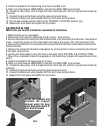
10. Thread the new power cord through the strain relief (the end with the ring terminal inside the
machine).
11. Connect the ground terminal using the reserved ground screw.
12. Connect the black and white (labeled HOT) to the 2-pole terminal block.
13. Flip the dual voltage selector switch to the 120/208V or 120/240V position (up).
14. Replace the front panel and tighten the (6) screws.
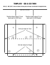
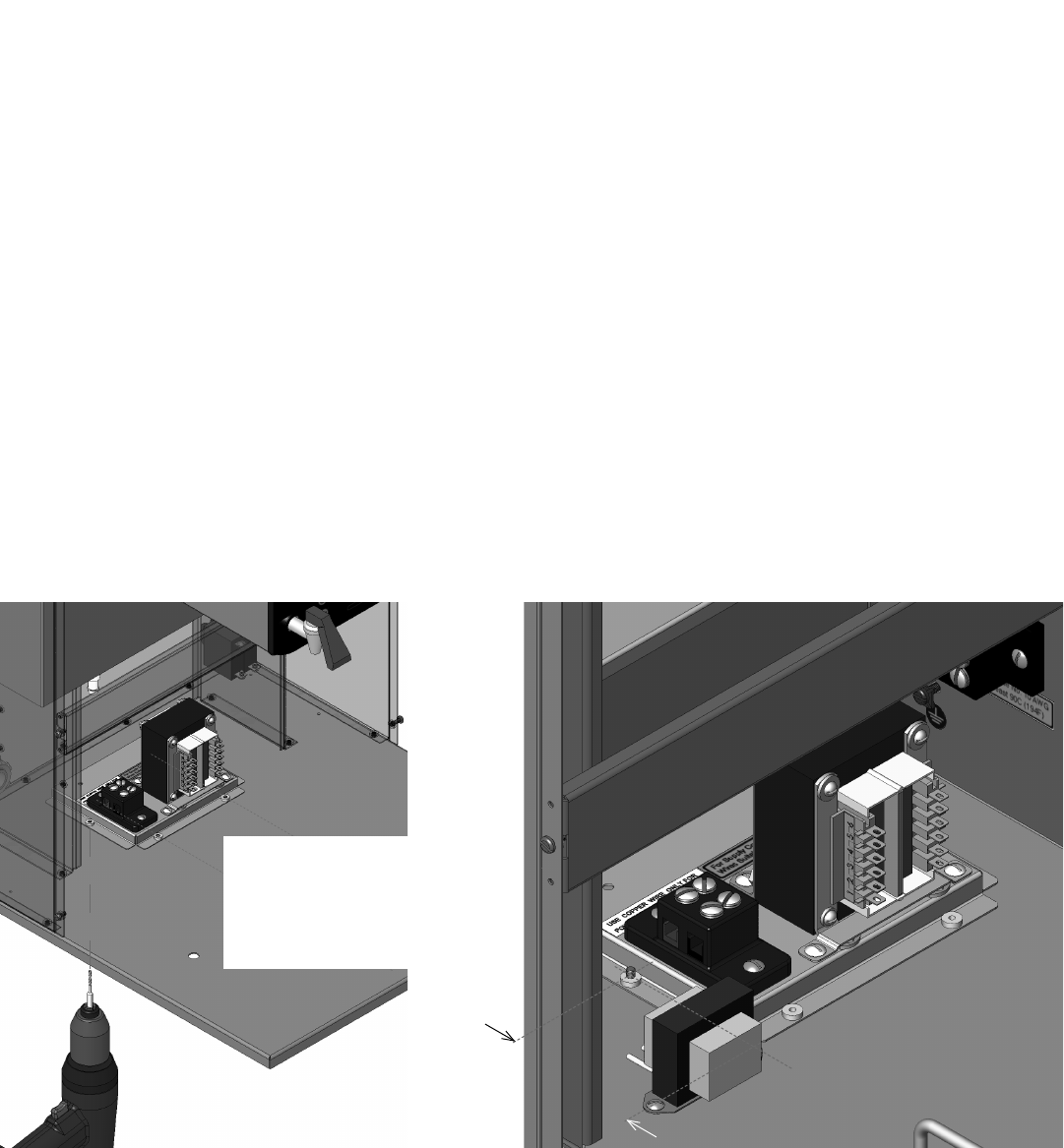
FIG 3
ICB TWIN/ITCB HV TWIN
208V 3-wire (no neutral) transformer conversion kit instructions
1. Make sure the unit is unplugged.
2. Remove the front panel by loosening the (6) screws. Save screws.
3. Remove the power cord wires from the terminal block, and remove the ground screw. Save ground
screw. Loosen the screws on the strain relief and remove the power cord. Discard power cord.
4. Remove the red/black 2-wire harness that connects the terminal block to the master on/off switch.
Discard harness.
5. Remove the component bracket (if equipped) by removing the 2 screws connecting the bracket
to the base. Save screws.
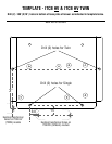
6. Use the drill hole pattern to drill (2) holes in the base. FIG 3 ICB TWIN, FIG 4 ITCB HV TWIN
7. Mount the component bracket (if equipped) to the transformer bracket with saved screws from
step 5.
8. Install the bracket to the base using (2) screws.
9. Refer to wiring diagram 42995.0001 to connect the 42947.0001 wire harness.
10. Thread the new power cord through the strain relief (the end with the ring terminal inside the
machine).
11. Connect the ground terminal using the reserved ground screw.
12. Connect the black and white (labeled HOT) to the 2-pole terminal block.
13. Replace the front panel and tighten the (6) screws.
Center the template and
straddle the support
channel under the base
plate. Mark/drill holes 5.0"
from back of brewer.
3˝
FIG 4