


Refreshment Center Parts Manual List of Figures
December 2005 i 7800041
List Of Figures
Section A: Exterior of door ................................................................................................2
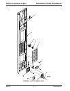
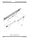
FIGURE 1 Exterior door Assy ........................................................................................... 2
FIGURE 2 Button Array Assy ............................................................................................4
Section B: Interior of door .................................................................................................6
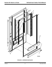
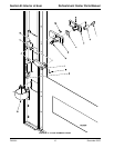
FIGURE 3 Interior Door Assy ............................................................................................6
FIGURE 4 Light Bracket Assy ...........................................................................................8
FIGURE 5 Lock Handle Assy ..........................................................................................10
FIGURE 6 Coin Cup .......................................................................................................12
FIGURE 7 Delivery Bin (1 of 4) .......................................................................................14
FIGURE 8 Delivery Bin (2 of 4) .......................................................................................16
FIGURE 9 Delivery Bin (3 of 4) .......................................................................................18
FIGURE 10 Delivery Bin (4 of 4) .......................................................................................20
FIGURE 11 SureVend ......................................................................................................22
Section C: Cabinet............................................................................................................ 24
FIGURE 12 Cabinet Assy .................................................................................................24
FIGURE 13 Cash Box Lock ..............................................................................................26
FIGURE 14 Door Hinge ....................................................................................................28
FIGURE 15 Lighting Channel ...........................................................................................30
FIGURE 16 Evaporator Fan Assy .....................................................................................32
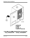
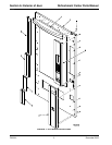
FIGURE 17 Dual Zone Components Version I Duct System ............................................34
FIGURE 18 Dual Zone Components Version II Duct System ...........................................36
FIGURE 19 Cabinet Legs .................................................................................................38
FIGURE 20 Base Plate .....................................................................................................40
Section D: Trays................................................................................................................ 42
FIGURE 21 Snack Tray Assy ........................................................................................... 42
FIGURE 22 Snack Tray Assy - Rear ................................................................................44
FIGURE 23 Candy Tray Assy ...........................................................................................46
FIGURE 24 Candy Tray - Rear .........................................................................................48
FIGURE 25 Bottle Tray .....................................................................................................50
FIGURE 26 Bottle Tray - Rear ..........................................................................................52
Section E: Refrigeration ...................................................................................................56
FIGURE 27 Evaporator Pan Assy..................................................................................... 56
FIGURE 28 Refrigeration Assy (1 of 2) .............................................................................58
FIGURE 29 Refrigeration Assy (2 of 2) .............................................................................60
Section F: Monetary and electronics ..............................................................................62
FIGURE 30 Monetary Assy............................................................................................... 62
FIGURE 31 PCB Housing .................................................................................................64
FIGURE 32 Coin Mech Bracket ........................................................................................66
FIGURE 33 Card Reader and Bill Validator Combinations ...............................................68
FIGURE 34 Power Panel Assy .........................................................................................71