


7. CR#24 ~ CR#27: display the present temperature (°F) of CH1~CH4 input signal.
8. CR#30 is the fault code register. Refer to the chart below.
Fault description Content b15~b8 b7 b6 b5 b4 b3 b2 b1 b0
Power source abnormal K1(H1) 0 0 0 0 0 0 0 1
Analog input value error K2(H2) 0 0 0 0 0 0 1 0
Setting mode error K4(H4) 0 0 0 0 0 1 0 0
Offset/Gain error K8(H8) 0 0 0 0 1 0 0 0
Hardware malfunction K16(H10) 0 0 0 1 0 0 0 0
Digital range error K32(H20) 0 0 1 0 0 0 0 0
Average times setting error K64(H40) 0 1 0 0 0 0 0 0
Instruction error K128(H80)
Reserved
1 0 0 0 0 0 0 0
Note: Each fault code has the corresponding bit (b0~b7). Two or more faults may happen at the
same time. 0 means normal and 1 means fault happened.
9. CR#31: RS-485 communication address. Setting range is 01~255 and factory setting is K1.
10. CR#32: RS-485 communication baud rate: 4800, 9600, 19200, 38400, 57600 and 115200.
b0:4800bps, b1:9600bps (factory setting), b2:19200bps, b3:38400 bps, b4:57600 bps, b5:115200
bps, b6~b13: Reserved, b14: switch between low bit and high bit of CRC code (only for RTU mode)
b15=0: ASCII mode, b15=1: RTU mode. Communication format for ASCII mode is 7Bit, even bit, 1
stop bit (7 E 1), while for RTU mode is 8Bit, even bit, 1 stop bit (8 E 1).
11. CR#33: b0~b11: Used to reset the settings of CH1~CH4 to factory defaults.
b12~b15: defined the ERR LED, factory setting is b12~b15=1111.
12. CR#34: software version.
13. CR#35~ CR#48: Reserved for internal system use.
14. The corresponding parameters address H4064~H4095 of CR#0~CR#48 are provided for users to
read/write data via RS-485 communication.
A. Baud rate can be 4800, 9600, 19200, 38400, 57600, 115200bps.
B. MODBUS communication protocol can be either ASCII or RTU mode. Communication format
for ASCII mode is 7Bit, even bit, 1 stop bit (7 E 1), while for RTU mode is 8Bit, even bit, 1
stop bit (8 E 1).
C. Function code: 03H read data from register.
06H write 1pcs WORD into register.
10H write multiple WORD into register.
5 TEMPERATURE/DIGITAL CHARACTERISTIC CURVE
Temperature mode: (Centigrade)
+6000
+3000
-2000
+600-200
Digital Output
Temperature Input
C C
Temperature mode: (Fahrenheit)
+11120
+5560
-3280
+1112
-328
Digital Output
Temperature Input
F F
6 INITIAL PLC START-UP
LED display:
1. Upon power-up, the ERROR LED will light on for 0.5 seconds the POWER LED will light
on continuously.
2. POWER LED on and ERROR LED off means No Error.
Low Voltage error (lower than 19.5V), ERROR LED will blink continuously till the power
supply goes above 19.5V.
3. DVP04PT-H is connected to PLC MPU in series = RUN LED on MPU will be lit and A/D
LED or D/A LED should blink.
4. After receiving the first RS-485 instruction the A/D LED or D/A LED will blink.
5. If the input or output exceeds the upper or lower bounds, then the ERROR LED will blink.
Example:
M1000
FROM K0
= H402 D0
TO K0
FROM K0
FROM K0
FROM K0
FROM K0
FROM
M1002
Explanation:
Read the model type of extension module K0 (should be H0402 for DVP04PT-H model type).
The average values of CH1~CH4 saved in D10~D13 are written into CR#2~CR#5.
For DVP04PT-H model. The read average temperature (
°C) of CH1~CH4 (4 data) from CR#6~CR#9
and saved to D20~D23.
The read average temperature
(°F) of CH1~CH4 (4 data) from CR#12~CR#15 and saved into
D24~D27.
The read present temperature (
°C) of CH1~CH4 (4 data) from CR#18~CR#21 and saved into
D30~D33.
The read present temperature
(°F) of CH1~CH4 (4 data) from CR#24~CR#27 and saved into
D34~D37.
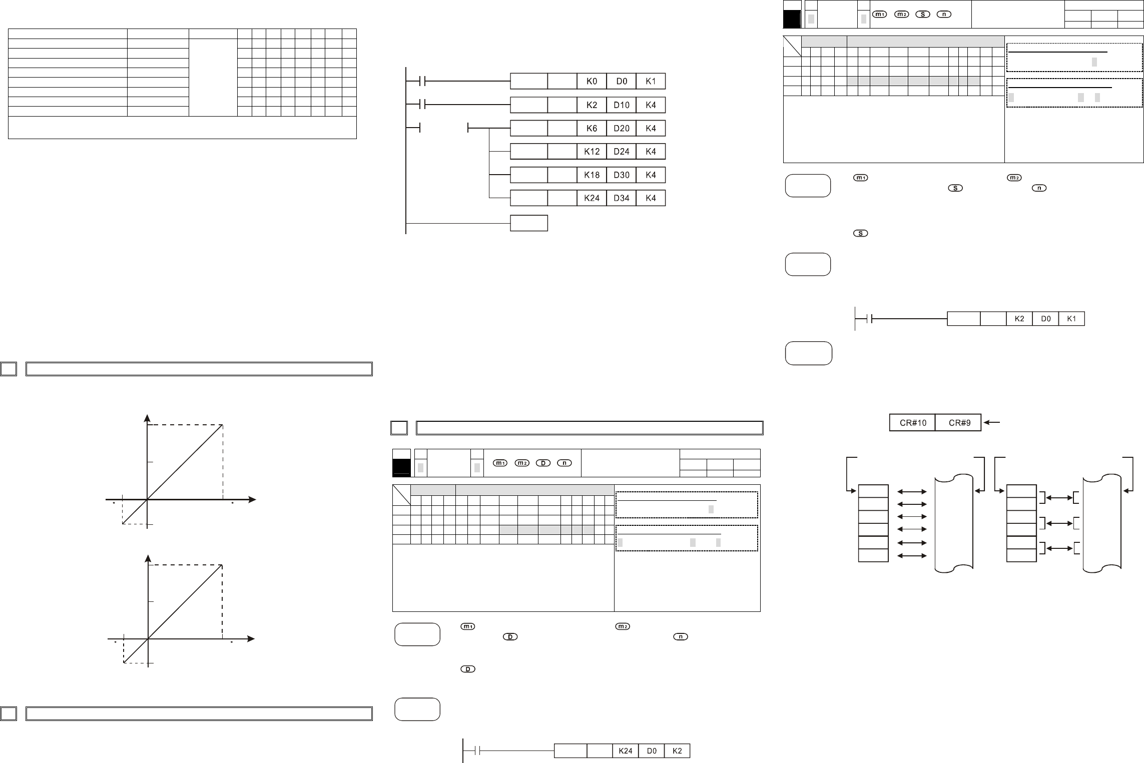
7 RELATED INSTRUCTIONS EXPLANATION
API
Applicable model
ES EP EH
78
D
FROM
P
Read special module CR
data
Bit device Word device
X Y M S K H KnX KnY KnM KnS T C D E F
m
1
¼ ¼
m
2
¼ ¼
D
¼ ¼ ¼ ¼ ¼ ¼ ¼ ¼
n
¼ ¼
Note: The usage range of operand m
1
is 0~7.
The usage range of operand m
2
: ES/EP: 0-48,
EH: 0-254.
The usage range of operand n: ES/EP: n=
1~(49-m2), EH: 1~(255-m2).
ES series model doesn’t support pulse
execution instruction (FROMP, DFROMP).
16-bit instruction (9 STEPS)
FROM
Continuous
execution
FROMP
Pulse
execution
32-bit instruction (17 STEPS)
DFROM
Continuous
execution
DFROMP
Pulse
execution
Flag: When M1083 On, it allows
to enable interrupt during
FROM/TO. Refer to the
below for detail.
Command
Explanation
: the module number you are probing. : the number of Controlled Registers
to be read.
: the data register location for storing data. : the number of CRs
to read at one time.
DVP-series PLC uses this instruction to read CR data of each special module.
: When assigning bit operand, K1~K4 are used for 16-bit and K5~K8 are used
for 32-bit.
Please refer the following footnote for calculating of special module number.
Program
Example
Read the content of CR#24 and CR#25 of module#0 and save it into D0 and D1
when n=2.
Instruction will be executed when X0=ON. However, nothing will occur and the
stored data has no change when X0=OFF.
X0
FROM K0
API
Applicable model
ES EP EH
79
D
TO
P
Special module CR
data write
Bit device Word device
X Y M S K H KnX KnY KnM KnS T C D E F
m
1
¼ ¼
m
2
¼ ¼
S
¼ ¼ ¼ ¼ ¼ ¼ ¼ ¼ ¼ ¼ ¼
n
¼ ¼
Note: The usage range of operand m
1
is 0~7.
The usage range of operand m
2
: ES/EP: 0-48,
EH: 0-254.
The usage range of operand n: ES/EP: n=
1~(49-m2), EH: 1~(255-m2).
ES series does not support pulse execution
instruction (TOP, DTOP)
16-bit instruction (9 STEPS)
TO
Continuous
execution
TOP
Pulse
execution
32-bit instruction (17 STEPS)
DTO
Continuous
execution
DTOP
Pulse
execution
Flag: When M1083=On, it
allows to insert interrupt
during FROM/TO. Refer to
following for detail.
Command
Explanation
: the module number you are probing. : the number of Controlled
Registers to be written to.
: the data to write. : the number of CR to be
written to in one time.
DVP-series PLC uses this instruction to write data to Controlled Registers of
special modules.
: When assign the bit operand, K1~K4 are used for 16-bit and K5~K8 are
used for 32-bit.
Program
Example
Using the 32-bit instruction DTO. The program will write D11 and D10 into CR#3
and CR#2 of special module#0. DTO only allows one group of data to be written at
a time (n=1).
The instruction is executed when X0=ON. Nothing will occur and the stored data
will have no change when X0=OFF.
X0
DTO K0
Footnote
The rules for adding multiple special modules to a Main Processing Unit:
m1: The maximum number of special modules attached to an MPU is 8. The
module closest to the MPU is 0 and the module furthest from the MPU is 7.
m2: The number of Controlled Registers (CR) built in is 49. (#0~#48).
FROM/TO instruction read/write one CR at a time, while DFROM/DTO
instruction read/write two CR at a time. Example below:
Upper 16-bit Lower 16-bit
Assigned CR numer
(Access16-bit if n=2, or 32-bit if n=1. Same controlled registers are accessed).
D0
D1
D2
D3
D4
D5
D0
D1
D2
D3
D4
D5
CR#5
CR#6
CR#7
CR#8
CR#9
CR#10
CR#5
CR#6
CR#7
CR#8
CR#9
CR#10
Assigned
Equipment
Assigned
CR
Assigned
Equipment
Assigned
CR
16-bit command when n=6 32-bit command when n=3
In ES series models, flag M1083 is not provided. When FROM/TO instruction is
executed, all interrupts (including external or internal interrupt subroutines) will be
disabled. All interrupts will be executed after FROM/TO instruction is completed.
Besides, FROM/TO instruction also can be executed in the interrupt subroutine.
The function of the flag M1083 (FROM/TO mode exchange) provided in EP/EH
series models:
a. When M1083=Off, all interrupts (including external or internal interrupt
subroutines) will be disabled when FROM/TO instruction is executed. The
Interrupts will resumed after FROM/TO instruction complete. Please be
advised FROM/TO instruction can be executed in the interrupt subroutine.
b. When M1083=On, if an interrupt enable occurs while FROM/TO
instruction are executing, the interrupt FROM/TO instruction will be
blocked till the requested interrupt finish. Unlike M1080 off situation,
FROM/TO instruction cannot be executed in the interrupt subroutine.