


2
A few other radio brands (and other electronic devices) that meet the
NMEA 0183 standard won't need these adapters and you will have to
remove the resistor and diode to make those work. This is Wiring
Diagram B, which is described on page 4.
Consult your other device's owner’s manual, then read through all of
the following instructions before you begin. Use the installation
diagram most suited to your brand of radio or other device. If your
device manual indicates an RS-232 connection (i.e., a computer),
remove the resistor and diode and connect using Wiring Diagram B.
Most other connection types (TTL; NMEA + and NMEA –;
differential) will require Wiring Diagram A.
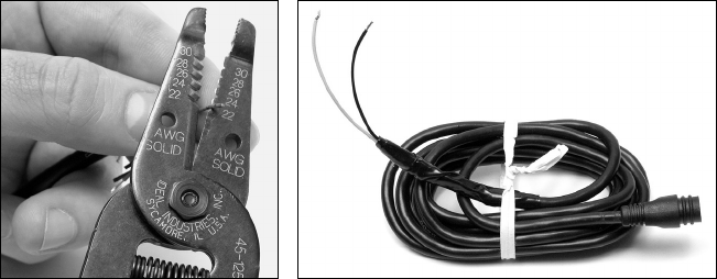
Recommended Tools and supplies
Recommended tools for this job include: wire pliers or wire stripper and a
wire cutter. Required supplies for this job include: two gray (18 gauge) or
blue (16 gauge) wire nuts and electrical tape. Supplies are not included.
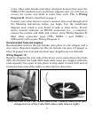
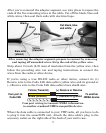
Wiring Diagram "A"
Begin by stripping the wire ends of the device you're connecting to the Cuda
240i. (You'll notice the Cuda 240i's data cable comes pre-stripped, with wire
ends exposed.) Use a pair of wire pliers to strip about 1/4-inch (6.35 mm) of
insulation from each of the radio's or other device's data wires.
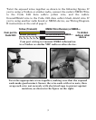
Strip the ends of the VHF radio's data wires. Connect them to the pre-
stripped wires of the Cuda 240i's data cable (shown right).