


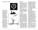
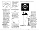
TREES IN THE WATER
IMPORTANT
The bracket sides will have to be
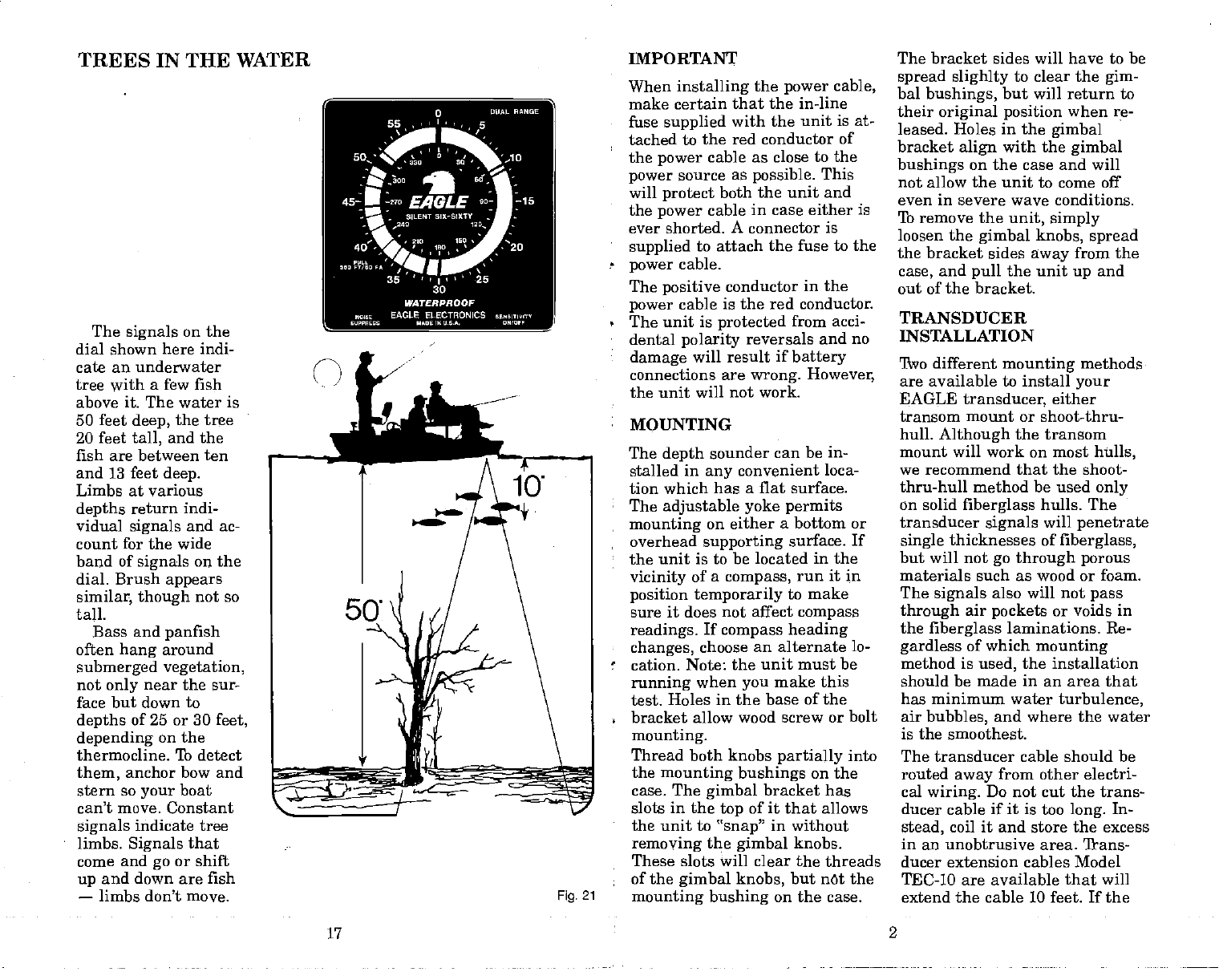
The
signals
on the
dial shown here indi-
cate an underwater
tree
with
a few fish
above it. The water is
50 feet
deep,
the tree
20 feet
tall,
and the
fish are between ten
and 13 feet
deep.
Limbs at various
depths
return indi-
vidual
signals
and ac-
count for the wide
band of
signals
on the
dial. Brush
appears
similar, though
not so
tall.
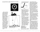
Bass and
panfish
often
hang
around
submerged vegetation,
not
only
near the sur-
face but down to
depths
of 25 or 30
feet,
depending
on the
thermocline. To detect
them,
anchor bow and
stern so
your
boat
can't
move.
Constant
signals
indicate tree
limbs.
Signals
that
come and
go
or shift
up
and down are fish
—
limbs don't move.
When
installing
the
power
cable,
make certain that the in-line
fuse
supplied
with the unit is at-
tached to the red conductor of
the
power
cable
as close to the
power
source as
possible.
This
will
protect
both the unit and
the
power
cable
in case either is
ever shorted. A connector is
•
supplied
to attach the fuse
to the
-
power
cable.
The
positive
conductor
in the
power
cable is the red conductor.
•
The unit is
protected
from
acci-
•
dental
polarity
reversals and no
damage
will result if
battery
connections are
wrong.
However,
the unit will not work.
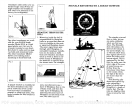
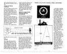
MOUNTING
The
depth
sounder
can be in-
stalled
in
any
convenient loca-
tion which has a
flat surface.
The
adjustable
yoke permits
mounting
on either
a bottom or
overhead
supporting
surface. If
the unit is
to be located in the
vicinity
of a
compass,
run it in
position temporarily
to make
sure it does not
affect
compass
readings.
If
compass
heading
•
changes,
choose
an alternate lo-
cation. Note:
the unit must be
running
when
you
make this
test. Holes
in the base of the
bracket allow wood screw or bolt
mounting.
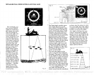
Thread both knobs
partially
into
the
mounting bushings
on the
case. The
gimbal
bracket has
slots
in
the
top
of it that allows
•
the unit to
"snap"
in without
removing
the
gimbal
knobs.
These slots will clear the threads
of the
gimbal knobs,
but net the
Fig.
21
mounting bushing
on the case.
spread slighlty
to clear the
gim-
bal
bushings,
but will return to
their
original position
when re-
leased. Holes in the
gimbal
bracket
align
with the
gimbal
bushings
on the case and will
not allow the unit to come ofT
even in severe wave conditions.
lb remove the
unit, simply
loosen the
gimbal knobs, spread
the bracket sides
away
from the
case,
and
pull
the unit
up
and
out of the bracket.
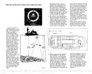
TRANSDUCER
INSTALLATION
Two different
mounting
methods
are available to install
your
EAGLE
transducer,
either
transom mount or shoot-thru-
hull.
Although
the transom
mount will work on most
hulls,
we recommend that the shoot-
thru-hull method be used
only
on solid
fiberglass
hulls. The
transducer
signals
will
penetrate
single
thicknesses of
fiberglass,
but will not
go through porous
materials such as wood or foam.
The
signals
also will not
pass
through
air
pockets
or voids
in
the
fiberglass
laminations. Re-
gardless
of which
mounting
method is
used,
the installation
should be made in an area that
has minimum water
turbulence,
air
bubbles,
and where the water
is the smoothest.
The transducer cable should be
routed
away
from other electri-
cal
wiring.
Do not cut the trans-
ducer cable if
it
is too
long.
In-
stead,
coil it and
store the excess
in an unobtrusive area. 'frans-
ducer extension cables Model
TEC-10 are available that will
extend
the cable 10 feet. If the
17
2
PDF compression, OCR, web-optimization with CVISION's PdfCompressor