


3
MODEL 410VP CALIBRATION
The sensor is calibrated at the factory and does not require initial user-calibration. Simply configure the analyzer
to accept a four-electrode sensor and enter the cell constant and calibration factor printed on the label.
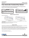
After a period of service, the sensor may require calibration. The sensor can be calibrated against a solution
having known conductivity or against a referee meter and sensor. If using a standard solution, choose one
having conductivity greater than 500 uS/cm. Do not use standard solutions having conductivity less than
100 uS/cm. They are susceptible to contamination by atmospheric carbon dioxide, which can alter the
conductivity by a variable amount as great as 1.2 uS/cm (at 25°C). Calibration changes the cell constant
only, not the calibration factor. If you wish to change the calibration factor, consult the factory. For more
information about calibrating contacting conductivity sensors see application sheet ADS 43-024 available
on the Rosemount Analytical website at www.rosemountanalytical.com.
SETUP AND CALIBRATION
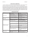
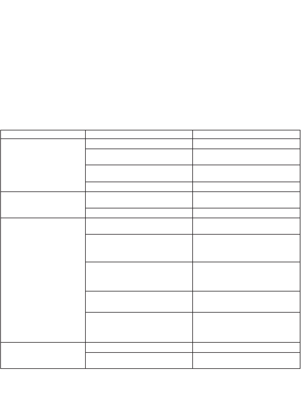
TROUBLESHOOTING
PROBLEM PROBABLE CAUSE SOLUTION
Off-scale reading
Wiring is incorrect.
Verify wiring.
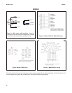
RTD is open or shorted.
Check RTD for open connections or
shorts. See Figure 1.
Sensor is not in process stream.
Be sure sensor is completely submerged
in process stream.
Variopol cable is not properly seated. Loosen connector and reseat.
Noisy reading
Sensor is improperly installed in process
stream.
Be sure sensor is completely submerged
in process stream.
Variopol cable is not properly seated. Loosen connector and reseat.
Reading seems wrong (lower
or higher than expected)
Bubbles trapped on sensor.
Be sure sensor is installed so that air
cannot become trapped against it.
Wrong temperature correction algorithm.
Check that temperature correction algo-
rithm is appropriate for the sample. See
the analyzer manual for more information.
Wrong cell constant. Wrong calibration
factor.
Verify that the correct cell constant and
calibration factor have been entered in the
analyzer. See the analyzer manual for
more information.
Bottom of sensor is too close to pipe
wall.
Maintain at least 1.0 in (25 mm) clearance
between bottom of sensor and opposite
pipe wall.
Temperature reading in error
Disconnect red and white RTD wires.
Measure resistance across leads, which
should be about 1100Ω at room
temperature.
Sluggish response
Electrodes are fouled. Clean electrodes.
Sensor is installed in dead area in
process piping
Move sensor to a location more repre-
sentative of the process liquid.