


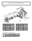
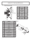


IntelliGear Plus™ Variable Speed MD Gearmotors
10
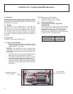
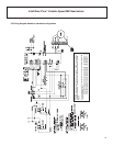
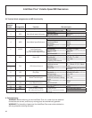
3.4 Terminal block assignments and MD functionality
Controller
Terminal
Number Designation Function Characteristics
1 10V +10V analog internal source Accuracy ± 2%
Maximum output current 30 mA
Voltage input
2 ADI1 Hand Mode Speed Reference Full scale voltage 10 V ± 2%
** Input Impedance 95 kΩ
3 0V Logic circuit common 0V
Current input
Current range 0 to 20 mA ± 5%
4 ADI2 Auto Mode Speed Reference Input impedance 500 Ω
Resolution 10 bits
Sampling 6 ms
Logic input (if connected to the +24 V
6 ADIO3 Fault Signal Input Threshholds “0”:<5V-”1”; >10V
From Pump Operation Voltage range 0 to +24V
Run Dry and/or High Pressure Load 95 kΩ
Input threshold 7.5V
Characteristics Digital output 1
7 DIO1 Alarm LED Threshholds “0”:<5V-”1”; >10V
Voltage range 0 to +24V
Sampling/refreshment 2 ms
5 Output current 10 mA in total
Overload current 33 = 150mA, 31/32 = 50mA
24V +24V internal source Accuracy ± 5%
11 Protection Current limiting and overload
fault trip
Logic input 2 Characteristics Logic input (positive logic)
8 DI2 Run/Stop Threshold “0”:<5V-”1”; >10V
Voltage range 0 to +24V
Logic input 3
Motor Thermal Input
Sampling/refreshment 2 ms
9 DI3 Absolute maximum voltage 0 to +35V
range
Logic input 4
Hand Mode Selectior
Load 15 kΩ
10 DI4 Input threshold 7.5V
Voltage range 9 to + 35V
12 ENA Enable Impedance 820 Ω
13 RL1 Drive Healthy Contact
N/C after start-up if OK
Characteristics
250VAC maximum contact
current
NO single pole contact
14 RL2 4 A, resistive load
2 A inductive load
** Performs scaling function when drive is programmed for full PI mode of operation
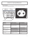
4. Commissioning
WARNING! Before switching on the IntelliGear Plus unit, check that the electrical
connections are correct, and that any moving parts are mechanically guarded.
WARNING! For the safety of personnel, the IntelliGear Plus must not be switched on
with any protective covering removed.