


3
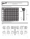
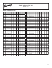
Lubrication
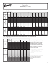
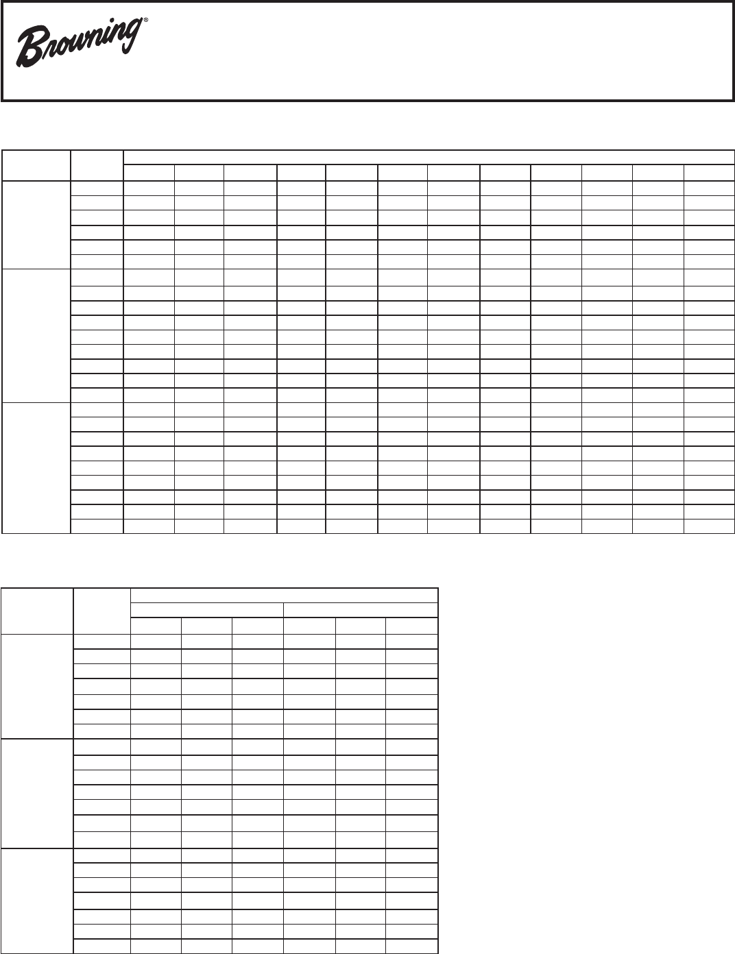
Oil Capacities (U.S. Quarts)
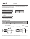
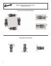
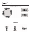
* refer to page illustrating mounting positions based on reduction stage(s) and gear frame to be checked or filled
One to Three Reduction
Stages
Gear
Frame
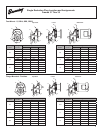
Mounting Positions *
B3 B5 B6 B7 B8 B52 B53 B54 V1 V3 V5 V6
ONE
(single reduction)
30 0.33 0.33 0.33 0.33 0.33 0.33 0.33 0.33 0.33 0.33 0.33 0.33
31 0.37 0.37 0.53 0.53 0.74 0.53 0.74 0.53 0.58 1.06 0.58 1.06
32 0.26 0.26 0.58 0.58 0.79 0.58 0.79 0.58 0.63 0.84 0.63 0.84
33 0.95 0.95 1.48 1.48 2.01 1.48 2.01 1.48 2.22 2.22 2.22 2.22
34 2.11 2.11 3.17 3.38 4.44 3.17 4.44 3.38 4.02 3.17 4.02 3.17
35 3.38 3.38 5.49 5.28 7.71 5.49 7.71 5.28 6.13 5.81 6.13 5.81
TWO
(Double Reduction)
30 0.63 0.63 0.63 0.63 0.63 - - - 0.63 0.63 0.63 0.63
31 0.63 0.63 1.00 0.90 1.16 - - - 1.22 1.48 1.22 1.48
32 1.00 1.00 1.85 1.64 2.38 - - - 2.38 2.85 2.38 2.85
33 1.69 1.69 3.49 3.12 4.70 - - - 4.75 4.65 4.75 4.65
34 3.49 3.49 7.40 4.97 7.08 - - - 7.93 7.93 7.93 7.93
35 5.49 5.49 10.46 8.98 13.95 - - - 15.53 14.48 15.53 14.48
36 8.45 8.45 12.69 19.02 23.77 - - - 25.36 25.89 25.36 25.89
37 13.74 13.74 22.19 33.81 40.15 - - - 44.91 43.85 44.91 43.85
38 17.96 17.96 26.42 53.89 61.30 - - - 68.68 64.46 68.68 64.46
THREE
(Triple Reduction)
30 0.74 0.74 0.74 0.74 0.74 - - - 0.74 0.74 0.74 0.74
31 0.63 0.63 1.30 0.90 1.16 - - - 1.22 1.48 1.22 1.48
32 1.00 1.00 2.43 1.64 2.38 - - - 2.38 2.85 2.38 2.85
33 1.69 1.69 4.62 3.12 4.70 - - - 4.75 4.65 4.75 4.65
34 3.49 3.49 7.40 4.97 7.08 - - - 7.93 7.93 7.93 7.93
35 5.49 5.49 13.21 8.98 13.95 - - - 15.53 14.48 15.53 14.48
36 8.45 8.45 15.85 19.02 23.77 - - - 25.36 25.89 25.36 25.89
37 13.74 13.74 28.50 33.81 40.15 - - - 44.91 43.85 44.91 43.85
38 17.96 17.96 45.44 53.89 61.30 - - - 68.68 64.46 68.68 64.46
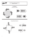
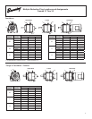
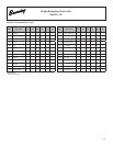
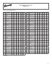
Combined Gear Units -
Stages
Combined
Gear Frame
Composition NOTE:
Primary Secondary These consist of 2 CbN gear units assembled
Frame Stages Type Frame Stages Type together. Each gear unit has a separate oil sump
FOUR
3254 32 Two CbN 30 Two CbN that is factory lled and requires monitoring
3374 33 Two CbN 30 Two CbN before start-up and during operation. The table
3484 34 Two CbN 31 Two CbN at left denes the gear size, and type for each
3594 35 Two CbN 31 Two CbN CbN gear of a specic “combined” gear reducer.
3604 36 Two CbN 32 Two CbN
3734 37 Two CbN 32 Two CbN Refer to the table above for oil volume based
3844 38 Two CbN 34 Two CbN on mounting position specied
FIVE
3255 32 Two CbN 30 Three CbN
3375 33 Two CbN 30 Three CbN
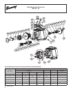
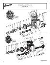
3485 34 Two CbN 31 Three CbN Oil sumps of frames 36, 37, and 38 are equipped
3595 35 Two CbN 31 Three CbN with a dipstick (with breather) for the
3605 36 Two CbN 32 Three CbN purposes of oil level monitoring when a unit
3735 37 Two CbN 32 Three CbN is not operating.
3845 38 Two CbN 34 Three CbN
SIX
3256 32 Three CbN 30 Three CbN
3376 33 Three CbN 30 Three CbN Oil sumps of frames 31 through 35 are equipped
3486 34 Three CbN 31 Three CbN with an oil level plugs for the purposes of
3596 35 Three CbN 31 Three CbN oil level monitoring when that unit is not
3606 36 Three CbN 32 Three CbN operating .
3736 37 Three CbN 32 Three CbN
3846 38 Three CbN 34 Three CbN