


1. Mount the SA-1 securely in upright position in an
open space, in direct contact with snowfall pattern
with a .5" (12.70mm) NPT mounting connector.
The unit is water-resistant, but it is not designed
to be submerged or immersed in water. Ensure
that the mounting location is close, less than
2.5 ft (76.20cm) to the electrical junction box.
See Fig. 4a &4b.
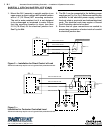
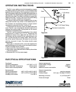
2. The SA-1 can be connected to the building power
supply as per Fig. 2 or Fig. 3. Before connecting the
controller to the electrical power supply, consult
the local, state or provincial, and national electrical
code. The electrical code may require a Ground
Fault Protection device to be used.
3. Ensure that all pipe connections are sealed to
prevent any penetration of water inside of conduit
or electrical junction box.
2 sa-1 Automatic Snow/Ice Melting Controller — Installation & Operation Instructions
SA - 1
AWG #12 RED/YELLOW
AWG #12 RED/YELLOW
AWG #18 BLACK
AWG #18 WHITE
OPTIONAL MANUAL SWITCH OR TIMER
SNOW MELTING
CABLE
OPTIONAL
ON/OFF
SWITCH
INSTALLATION FOR DIRECT CONTROL OF LOAD
* ELECTRICAL CODE MAY REQUIRE USE OF A GROUND FAULT PROTECTION DEVICE.
Figure 2 — Installation for Direct Control of Load
*Electrical code may require use of a ground fault protection device.
SA - 1
AWG #12 RED/YELLOW
AWG #12 RED/YELLOW
AWG #18 BLACK
AWG #18 WHITE
OPTIONAL
ON/OFF
SWITCH
COIL
120
VAC
OPTIONAL MANUAL SWITCH OR TIMER
SNOW MELTING
CABLE
INSTALLATION FOR CONTACTOR CONTROLLED LOAD (240 VAC)
* ELECTRICAL CODE MAY REQUIRE USE OF A GROUND FAULT PROTECTION DEVICE.
Figure 3 —
Installation for Contactor Controlled Load
*Electrical code may require use of a ground fault protection device.
www.easyheat.com
US T. (800) 537-4732 / F. (888) 324-2440
CAN T. (800) 794-3766 / F. (800) 361-4574
INSTALLATION INSTRUCTIONS