


IP242/SI
Page 2
GB
Instructions specific to hazardous area installations
Model numbers covered: MES3L/**** ('*' indicates options in construction, function and materials.)
The following instructions apply to equipment covered by certificate number TRL 03ATEX21034X:
1. The MES3L control unit may be connected to a transmitter located in a hazardous area. The MES3L control unit
must not itself be located in a hazardous area.
2. Installation of this equipment shall be carried out by suitably trained personnel, in accordance with the applicable
code of practice.
3. The user should not repair this equipment.
4. If the equipment is likely to come into contact with aggressive substances, it is the responsibility of the user to
take suitable precautions that prevent it from being adversely affected, thus ensuring that the type of protection is
not compromised.
Aggressive Substances
– e.g. acidic liquids or gases that may attack metals or solvents that may affect
polymeric materials.
Suitable Precautions
– e.g. regular checks as part of routine inspections or establishing from the
material’s data sheet that it is resistant to specific chemicals.
5. Wiring instructions:
(a) The MES3L must not be connected to a supply exceeding 250V r.m.s. or dc, or to apparatus containing a
source of voltage exceeding 250V r.m.s. or dc.
(b) The Intrinsically Safe outputs of the MES3L Control Unit may be connected to certified equipment used in a
hazardous area requiring category 1 equipment, with flammable gases and vapours with apparatus groups
IIC, IIB and IIA. No additional I.S. barrier is required.
(c) The fuse must only be replaced with the type specified.
(d) The intrinsic safe outputs must not be connected together.
6. Technical data:
(a) Materials of construction: Refer to Part numbering identification chart.
(b) Coding: II (1) G
[EEx ia] IIC
(c) Electrical:
Output Parameters: Terminal numbers 1 & 2: Uo: 20.5V, Io: 181mA, Po: 0.92W, Ci: 0µF, Li: 0 mH.
Terminal numbers 3 & 4: Uo: 20.5V, Io: 181mA, Po: 0.92W, Ci: 0µF, Li: 0 mH.
Terminal numbers 14, 15 & 16: Um: 250 Vrms.
Relay Contact ratings: U<250Vrms, I<5A, P<100VA
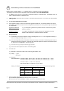
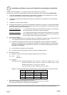
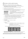
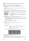
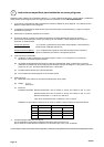
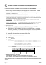
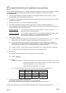
Cabling: The Capacitance and Inductance of the load connected must not exceed the following values:
Group Capacitance Inductance or L/R ratio
µF mH µH/ohm
IIC 0.203 1.08 38.5
IIB 1.33 4.34 154.1
IIA 5.12 8.68 308.3
7. Special conditions for safe use:
(a) The load/cable parameters shown above must be complied with.
(b) The control unit must be installed in a clean, dry and well controlled environment.
Please note that the safety instructions and certificates in this publication have been translated from English (United Kingdom).