


D2542 (RX100 S5) Technical Manual 23
Features Interfaces and connectors
3.7 Interfaces and connectors
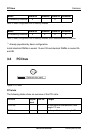
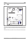
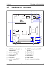
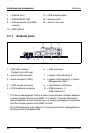
Figure 5: Schematic view of the system board D2542
1 = SATA 2 connector (only for
SATA version)
11 = SATA 1 connector (only SATA
version)
2 = power supply for I
2
C- 12 = System fan 3
3 = power supply ATX 13 = System fan 2
4 = system fan 5 14 = System fan 1
5 = front panel 15 = CSS module
6 = power supply ATX 12 V
(CPU)
16 = slots for memory modules
12 34
5
6
7
15
8
10
11
13
14
17
9
18
19
12
16
CPU
DIMM2B
DIMM1B
DIMM2A
DIMM1A
iRMC
Battery
CSS
indicate button
LSI
1064E