


6-3
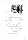
J802
J801
J611
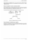
MD-9208
IF-9214
PTU-9335
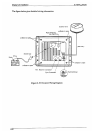
Cable
entry
Shield cover
Shield cover
Pan head screws
M4x8 7 pcs.
Pan head screws
M4x8 7 pcs.
Pan head screws
M4x8 4 pcs.
Gasket
Cable clamping plate
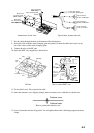
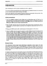
Antenna unit, inside view Signal cable, antenna unit side
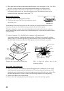
7. Pass the cable through the hole at the bottom of the radome base.
8. Secure the cable with the cable clamping plate and gasket. Ground the shield and vinyl wire by
one of the screws of the cable clamping plate.
9. Connect the wire to the RF unit.
10. Attach the EMC core supplied as shown below.
RF unit How to attach EMC core
11. Fix the shield cover. Do not pinch the cable.
12. Attach the radome cover, aligning triangle mark on radome cover with that on radome base.
Radome cover
Radome base
How to position the radome cover
13. Loosely fasten the radome fixing bolts. You will tighten them after confirming magnetron heater
voltage.
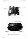
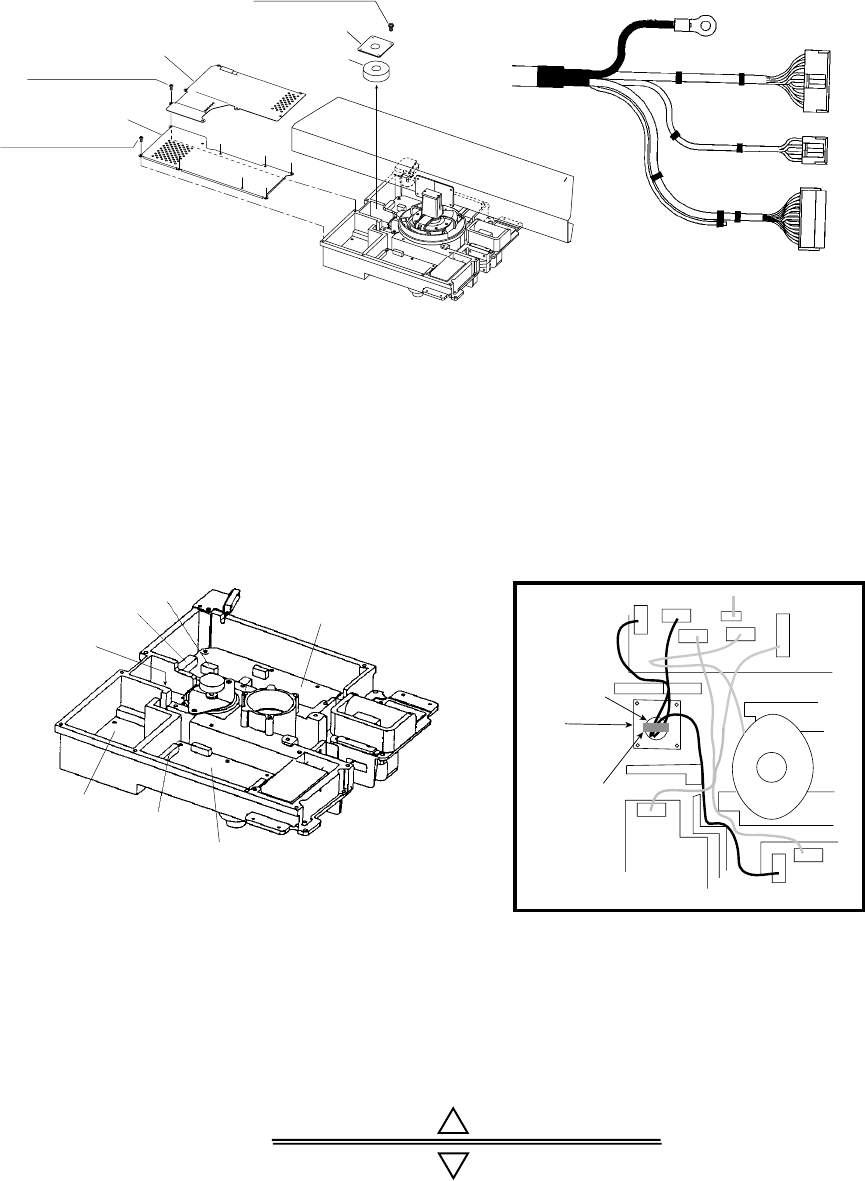
J806
J805
J803
J804
J802
J801
Motor
J613
J611
J1
EMC core
E04SS251512
(Above cable
clamping
plate)
Cable
entrance
IF9214IF9214
PTU-9335
MD9208
Cable
clamping plate
to one of the screws
of the cable clamping plate
9-pin connector:
to J801 on MD-9208
4-pin connector:
to J802 on MD-9208
13-pin connector:
to J611 on IF-9214