


3-8
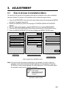
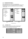
3.4 Checking Magnetron Heater Voltage
Magnetron heater voltage is formed on the PTU/MD Board of the antenna unit, and
preadjusted at the factory. Therefore no adjustment is required. However, check magnetron
heater voltage for confirmation as follows:
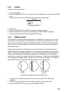
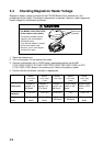
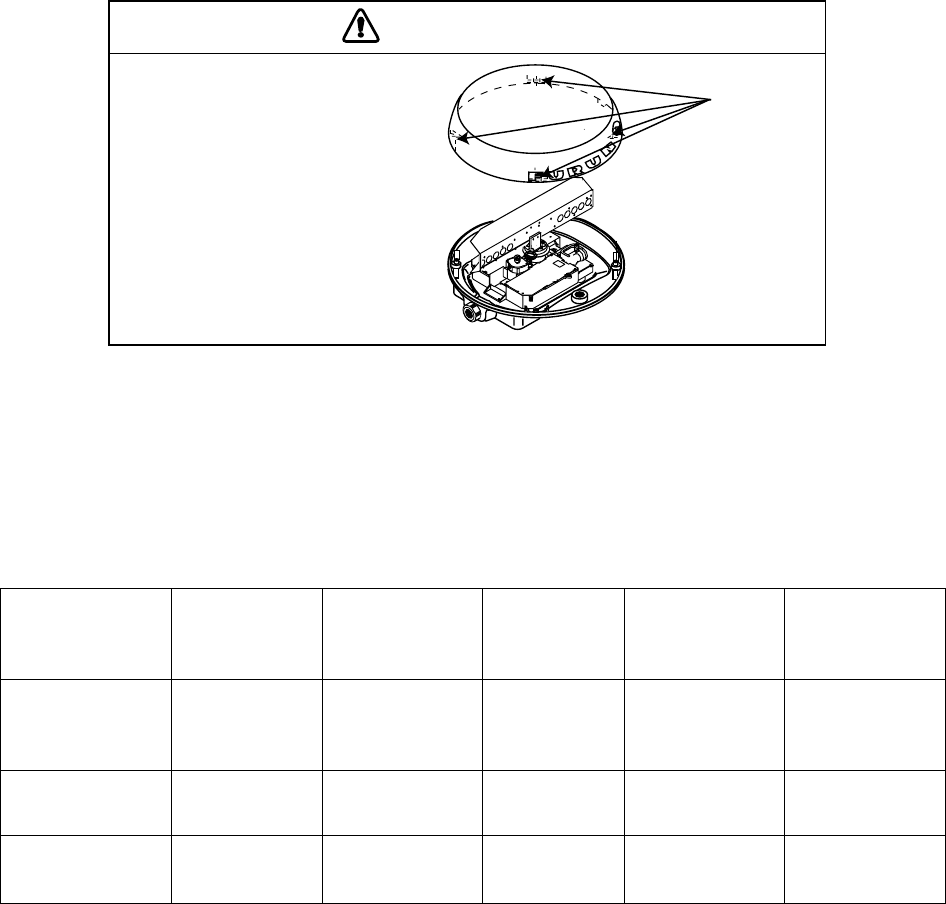
CAUTION
For MODEL1722/1722C/1723C,
lift the radome cover slowly.
The antenna radiator may be
caught by the screw holes in
the radome cover.
If you feel the radiator is caught
by the screw holes, lower
the cover, turn it a few degree
and then lift it again.
Screw holes
(4 places)
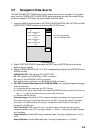
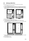
1. Open the antenna unit.
2. Turn on the power. Do not transmit the radar.
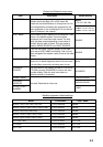
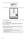
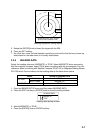
3. Connect a multimeter, set to 10VDC range, appropriate position on the MD
(1722/1722C/1723C/1742/1742C/1752/1752C/1753C/1762/1762C/1763C) or PTU
(1732/1732C/1733C) Board in the antenna unit. Refer to the table in below.
4. Confirm that the multimeter indication is appropriate.
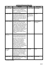
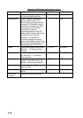
MODEL
1722/1722C/
1723C
MODEL
1732/1732C/
1733C
MODEL
1742/1742C
MODEL
1752/1752C/
1753C
MODEL
1762/1762C/
1763C
Check point
TP804#6 (+)
and #4 (-) on
MD Board
TP802#4 (+)
and #6 (-) on
PTU Board
TP804#3 (+)
and #2 (-) on
MD Board
J811#3 and #5
(GND) on MD
Board
J825#4 and #6
(GND) on RTB
Board
Multimeter
indication
7.9 to 8.1 V 7.4 to 7.6 V 8.0 to 8.2 V 7.6 V 7.4 to 7.6 V
Adjustment
point
VR801 on MD
Board
R106 on PTU
Board
VR801 on
MD Board
VR801 on
MD Board
VR801 on MD
Board