


27
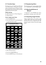
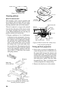
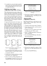
6. Remove the cable clamping plate by
un-fastening four screws and removing
a gasket.
Shield cover
Shield cover
Screws
7 pcs.
Screws
7 pcs.
Screws
6 pcs.
Shield cover
Screws
4 pcs.
Gasket
Cable clamping plate
Figure 6-5 Antenna unit, inside view
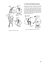
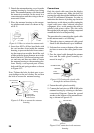
7. Pass the cable through the hole at the
bottom of the radome base.
8. Secure the cable with the cable
clamping plate and gasket. Ground the
shield and vinyl wire by one of the
screws of the cable clamping plate.
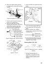
9. Connect the wire to the RF unit.
Figure 6-6 Signal cable, antenna unit side
Figure 6-7 RF unit
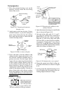
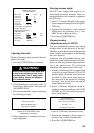
9. Attach the EMC core supplied as shown
below.
Figure 6-8 How to attach EMC core
11.Fix the shield cover. Do not pinch the
cable.
12.Attach the radome cover, aligning
triangle mark on radome cover with that
on radome base.
13.Loosely fasten the radome fixing bolts.
You will tighten them after confirming
magnetron heater voltage.
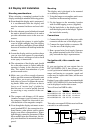
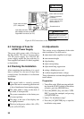
Mounting (Model 1932, 1942)
Figure 6-10 Typical antenna unit mounting
locations
1. Drill four fixing bolt holes (13
millimeters.), one cable entry hole
(approx. 50 mil-limiters dia.) in the
mounting platform. Seethe outline
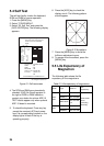
drawing.