


39
SPU-9180
DISPLAY
UNIT
J61
VIDEO
SOUNDER
Cable supplied
with radar
(connector assy.
03-1796(5))
Cable supplied
with video sounder
Solder and
tape.
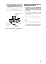
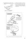
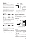
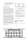
Figure 5-15 How to connect external
equipment to the OPTION connector
3) Cover signal cable at junction with dis-
play unit with silicone sealant.
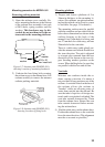
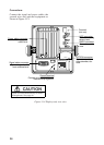
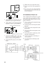
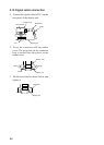
Distribution NAV data to the other
equipment
This radar can output NAV data received
from a navaid to an echosounder or video
plotter by making the modifications as
shown in below.
J55 (NMEA)
SPU9180
TLL, RSD
J61
Navaid
Echosounder
Video plotter
MODEL 821/841, FMD-811
The position data from navaid can be
used for the echosounder if a video
plotter is not connected.
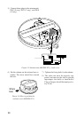
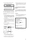
Procedure
1. Unfasten the nuts fixing the waterproof
connector to remove the covers of the
power and display unit.
2. Remove all connectors from SPU Board
(SPU-9180).
3. Unfasten three screws to remove the
board.
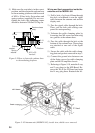
4. Remove JP3, R91 and R92 on the parts
side of SPU Board.
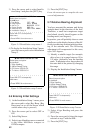
Navigation aid, video sounder
connection
If your navigation aid can output data in
NMEA 0183 data format, your vessel’s po-
sition in latitude and longitude, the range and
bearing to waypoint, speed, and course may
be input to this radar, and be seen in the bot-
tom text area.
Further, if your video sounder can output
depth in NMEA 0183 data format, depth can
be displayed on the navigation data dis-
played in graph form during stand-by.
You will need an NMEA cable:
For navaid;
Type Code no. Remarks
MJ-A6SPF0012-050 000-134-424 6P-6P(5m)
MJ-A6SPF0012-100 000-133-817 6P-6P(10m)
For E/S;
Type Code no. Remarks
MJ-A6SPF0011-050 000-132-224 6P-4P(5m)
MJ-A6SPF0011-100 000-132-336 6P-4P(10m)
Two NMEA connectors are provided at the
rear of the display unit: the NMEA connec-
tor and the OPTION connector.
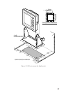
Heading Sensor Connection
Heading signal can be connected to the
“HDG” connector. 10 m cable assembly is
optionally available.
Type Code no. Remarks
MJ-A6SPF0007-100 000-125-237 C-2000
MJ-A6SPF0009-100 000-125-236 AD-100
The OPTION connector
To connect external equipment to the OP-
TION connector;
1) Remove the plastic cover on the connec-
tor.
2) Connect equipment to J61 on the SPU
Board as shown in Figure 5-15.