


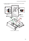
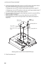

4. INSTALLING OPTIONAL EQUIPMENT
4-6
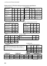
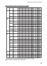
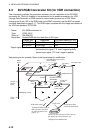
Setting method 1: DIP switch settings and gyrocompass specifications
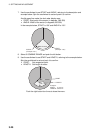
1) Gyrocompass type 2) Frequency
Gyrocompass
type
SW
1-4
SW
1-5
SW
1-6
JP1 Frequency
SW
1-7
SW
1-8
Remarks
AC
synchronous
OFF OFF OFF
#1, #2,
#3
50/60 Hz OFF OFF
AC synchronous
pulsating current
DC
synchronous
OFF OFF OFF
#2, #3,
#4
400 Hz ON OFF
AC synchronous
pulsating current
DC step ON OFF OFF
#4, #5,
#6
500 Hz OFF ON
AC synchronous
pulsating current
Full-wave
pulsating current
OFF ON OFF
#4, #5,
#6
DC ON ON
DC synchronous
DC step
Half-wave
pulsating current
ON ON OFF
#4, #5,
#6
3) Rotor Voltage (between R1 & R2) 4) Stator Voltage (between S1 & S2)
Rotor Voltage
SW
2-1
JP3
Stator
Voltage
SW
2-2
SW
2-3
JP2
20 to 45 VAC ON #2
20 to 45 VAC, or
20 to 60 VDC
ON OFF #2
30 to 70 VAC OFF #2
30 to 70 VAC, or
40 to 100 VDC
OFF OFF #2
40 to 90 VAC ON #1
40 to 90 VAC ON OFF
#1
60 to 135 VAC OFF #1
60 to 135 VAC OFF OFF
#1
5) Ratio 6) Supply Voltage
Ratio
SW
1-1
SW
1-2
SW
1-3
Stator
Voltage
JP4 JP5
360X OFF OFF OFF 20 to 45 VAC, or 20 to 60 VDC #2 #2
180X ON OFF OFF 30 to 70 VAC, or 40 to 100 VDC #1 #1
90X OFF ON OFF
36X ON ON OFF
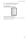
7) AD-10 format data 8) NMEA-0183
Tx interval Tx interval and Output sentence
Select data transmitting interval for ports 1 to 6 with jumper
wires JP6 and JP7: #25 for 25 ms, #200 for 200 ms.
Tx
interval
SW
2-5
SW
2-6
Output
sentence
Note: The Tx interval is available in 25 msec or 200 msec. 1 s OFF OFF HDT+VHW
Use 25 msec for radar. 200 ms ON OFF HDT
100 ms OFF ON HDT
25 ms ON ON HDT
9) NMEA-0183
Version no.
10) NMEA-0183
Baud rate
11) Power fail
detection
12) Stator signal
breaking detection
Version no. SW3-1 Baud rate SW3-2 Talker SW3-3
Detection
SW2-7
1.5 OFF 4860bps OFF Disable OFF
Execute
OFF
2.0 ON 38400bps ON Enable ON
No execute
ON
(Use OFF for radar.)
SW2-4: factory use only
SW3-4: not used