


3. SETTING AND ADJUSTMENT
3-12
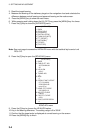
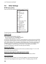
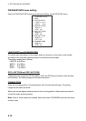
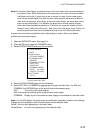
OWN SHIP INFO menu setting
Open the OWN SHIP INFO menu by pressing the [5] key on the INITIALIZE menu.
[OWN SHIP INFO]
1 BACK
2 LENGTH/WIDTH
LENGTH 100 m
WIDTH 50 m
3 SCANNER POSN
BOW 0 m
PORT 0 m
4 GPS1 ANT POSN
BOW 0 m
PORT 0 m
5 GPS2 ANT POSN
BOW 0 m
LEFT 0 m
6 CONNING POSN
BOW 0 m
PORT 0 m
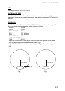
LENGTH/WIDTH and SCANNER POSN
To inscribe own ship shape on the screen when you choose it on the menu, enter length
and width of the ship and antenna position from the bow and left sides.
The setting ranges are as follows.
LENGTH: 0 to 999 m
WIDTH: 0 to 999 m
BOW: 0 to 999 m
PORT: 0 to 999 m
GPS 1 ANT POSN and GPS 2 ANT POSN
These items are needed for AIS information. Enter the GPS antenna position from the bow
and left sides. The setting ranges are the same as above.
CONNING POSN
Enter the conning position in the wheelhouse, from the bow and left sides. The setting
ranges are the same as above.
When you set the display reference point to the conning position, these values are used to
correct the radar antenna position.
Note: If two or more radars are installed, items other than 3 SCANNER should be the same
on each radar.