


1. MOUNTING
1-21
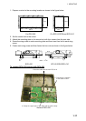
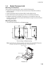
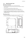
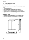
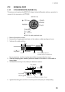
1.6 Chart Processor Unit
Mounting considerations
When selecting a mounting location, keep in mind the following points:
• Locate the processor unit away from heat sources because of heat that can build up
inside the cabinet.
• The vibration at the mounting location should be minimum.
• Locate the equipment away from places subject to water splash and rain.
• Leave sufficient space at the sides and rear of the unit to facilitate maintenance.
• A magnetic compass will be affected if the processor unit is placed too close to the
magnetic compass. Observe the compass safe distances on page ii to prevent deviation
of a magnetic compass.
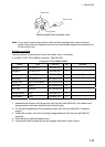
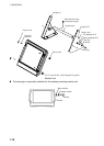
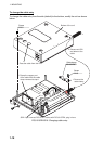
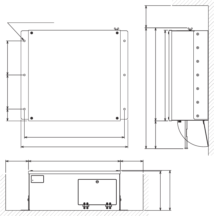
Mounting procedure
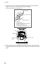
1. Attach two mounting plates to the processor unit with 14 screws (M4x8, supplied).
2. Fix the unit with six M6 bolts, or self-tapping screws (local supply).
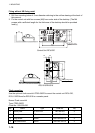
6-φ8 FIXING HOLES
399
410
532 #100
440
±
1
470
52
150
±
1 150
±
1
#100 404 #100
173
176
(122)
PROCESSOR UNITPROCESSOR UNIT