


2-6
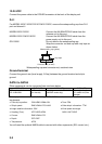
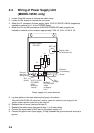
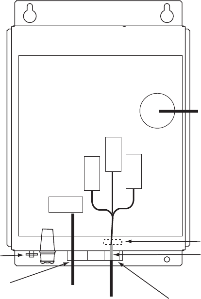
2.4 Wiring of Power Supply Unit
(MODEL1953C only)
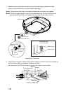
1. Loosen three M4 screws to remove the cable clamp.
2. Loosen six M4 screws to remove the unit cover.
3. Attach the VL connector of power supply cable VL3P-VV-S2X2C-AA050 (supplied as
installation material) to J1 on the POWER Board.
4. Attach the VH and NH connectors of MJ-B24LPF0009-050 cable (supplied as
installation material) to the locations appropriately; VH9: J3, VH4: J4, NH13: J5.
VL-3
VL3P-VV-S2X
2C-AA050
cable
(to ship's
mains)
MJ-B24
LPF0009-050
cable
(to display
unit)
Slot
(large)
Slot
(small)
POWER Board
19P1006
ANT (J8)
Signal cable
(to antenna unit)
J1
Ground
terminal
(Wing bolt)
V
H
9
N
H
13
V
H
4
J3
J4
J5
Shield
Cable tie
(if necessary)
Power supply unit, cover removed
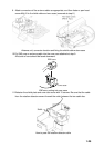
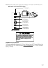
5. Lay two cables on the slots referring the figure in the above.
When MJ-B24LPF0009-050 cable has a tension, fasten the cable tie (local supply) to the
position shown above to avoid pulling the cable off.
6. Reattach the unit cover (removed at step 2).
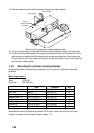
7. Reattach the cable clamp (removed at step 1) to fix two cables.
8. Connect the signal cable to ANT port on the power supply unit.
9. Connect the ground wire (local supply, IV-2sq) between the ground terminal and ship’s
ground.