


JANUARY/FEBRUARY 2008 OCEAN NAVIGATOR 55
www.oceannavigator.com
54 OCEAN NAVIGATOR JANUARY/FEBRUARY 2008
www.oceannavigator.com
50 cm/pixel). Areas where
the images contain useful
shallow water bottom
details are made progres-
sively transparent, pre-
senting both photo and
navigation chart informa-
tion. Areas where the
photo contains no useful
navigation information are
made entirely transparent,
eliminating possibly con-
fusing images of objects
that were on the water
when the satellite image
was created and assuring
that all charted navigation
information is clearly in
view.
The system’s split screen
options, single, dual, three
or four windows, allow
simultaneous side-by-side
viewing of raster and vec-
tor charts, with photo
images fused with both
views. The Ethernet-con-
nected Furuno FA 30/50
synthesized AIS receiver
can present information
from up to 100 AIS-
include a 4 kw/3.5 foot, 48
nm, 6 kw/4 foot, 64 nm,
12 kw, 72 nm or 25 kw
with 4- or 6-foot antennas,
maximum range 96 nm.
The digital signal pro-
cessing (DSP) technology
employed in these new
units (and used to great
advantage in Furuno
sonar/fish finders) signifi-
cantly improves the radar’s
ability to detect and accu-
rately visualize small, often
difficult to detect targets.
Small boats and navigation
aids with very limited radar
cross sections are clearly
imaged. The on screen
radar image clearly shows
the effectiveness of the new
signal processing circuits in
suppressing antenna side-
lobe response and in auto-
matically managing main
bang response.
Automatic radar plotting
aid (ARPA), previously a
10-target tracking option
on Furuno radar sets in this
category is now standard
and is able to simultane-
ously track up to 30 tar-
gets. All tracked targets
within the selected range
will appear on both radar
screens when operating as a
dual range radar. All of the
AIS targets (up to 100) are
available on both screens.
The new UHD radars
are remarkably easy to
install since the entire radar
system, including the
receiver and all signal pro-
reporting vessels on the
chart screen and when
desired on the radar image.
Vessels that present a possi-
bility of a close approach
or collision can be tracked
with automatic alerting for
those whose tracks portend
a close approach or possi-
bility of collision. The use
of a frequency synthesizer
in the AIS receiver assures
that the unit will be able to
operate on other than the
two standard AIS-reporting
channels (87B and 88B) if
required by area specific
regulations.
Radar that looks twice
The most impressive fea-
ture of the new NavNet 3D
UHD radar equipment is
its unique ability to per-
form like two separate
radar sets, each scanning at
whatever ranges are appro-
priate for the navigation
situation. Unlike previous
dual range radar systems
whose performance was
limited by the need to use
the pulse length required
for the longest selected
range, the UHD manages
the transmitted pulse
length for each range inde-
pendently, eliminating any
performance compromise.
The radar’s look twice
simultaneous dual range
capability is achieved by
double pulsing the mag-
netron, matching the dura-
tion of each alternate
transmitted pulse to the
selected range.
The full range of opera-
tor controls, range, gain,
sea state, interference rejec-
tion, rain suppression,
echo stretch, target trail,
variable range marker, elec-
tronic bearing line, etc.,
are available individually
for both ranges when the
system is operating in dual
range mode. Each radar
display can be operated
with an independent vessel
offset setting. The radar
image can be displayed in a
single, split, three or four
screen format and can be
overlaid on the chart/satel-
lite photo image. The
radar’s performance is
additionally aided by auto-
matically matching the
antenna rotation or sweep
speed to the longest range
in use (required to accom-
modate the longer pulse
lengths needed for longer
ranges), 48 rpm for short
ranges, 36 rpm for middle
distances and the standard
24 rpm for long ranges.
The new UHD radars
are available with RF
power ratings from 2 to 25
kw. Two radome antenna
models are available, 2 kw,
18-inch diameter, 24 nm
and 4 kw, 24-inch diame-
ter, 36 nm maximum
range. The radomes are a
new wind tunnel proven,
low aerodynamic drag
design. Open array models
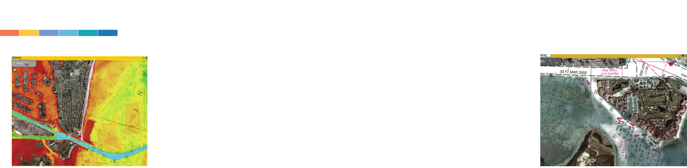
NavNet 3D com-
bines sat photos
with electronic
charts and colorized
depth shading.
Another exam-
ple of how the
system can ren-
der sat photos
and raster
charts.
cessing electronics are
housed in the antenna unit
and connect to the NavNet
3D system using an Ether-
net cable and a pair of 48-
volt DC power wires. Any-
one who has dealt with the
multi-conductor cable of
20-plus single wires and a
miniature coax will
applaud Furuno’s use of a
single, easy-to-install Eth-
ernet cable. Each radar (or
radars) and the majority of
the other sensors used in
the system are assigned
unique IP addresses, great-
ly simplifying setup, the
addition of sensors and
problem analysis if the
need arises. Two NMEA
2000 connectors provided
on the antenna housing
make it possible to connect
devices such as GPS
receivers, masthead wind
instruments or the Furuno
Weather Station to the sys-
tem network without the
need to run additional
cables.
The series of manual
timing/tuning adjustments
formerly required on the
installation of a radar is
now accomplished auto-
matically. The only manual
adjustment required at ini-
tial startup, matching the
radar’s lubber line to the
vessel’s longitudinal axis, is
accomplished at the radar
display.
The black box version of
the NavNet 3D system can
support up to 10 multi-
function display screens.
The black box system’s
central processor supports
an extended mode in
which the data output is
shared across two screens,
providing a range of dis-
play choices from two
large individual screens to
as many as eight screen
windows. Control of each
display window (in both
the single unit and black
box versions of the system)
is accomplished by moving
the cursor into the bound-
ary of the screen to be
controlled. No additional
control actions are
required. Highlighting the
boundary of the active
window signifies that the
controls are assigned to
that window.
Painless system inte-
gration
The majority of ancillary
sensors for the NavNet 3D
system, including the Sir-