


2 GMI 10 Installation Instructions
Step 1: Select a Location for the GMI 10
Consider the following when you select an installation location:
Provides optimal viewing as you operate your vessel.
Allows easy access to the keypad on the GMI 10.
Is strong enough to support the weight of the GMI 10 and protect it from excessive vibration or shock.
Allows room for the routing and connection of the cables. There should be at least a 3 inch (8 cm) clearance behind
the case.
Is at least 9
1
/
2
in. (241 mm) from a magnetic compass, to avoid interference.
Mount the GMI 10 in an area that is not exposed to extreme temperature conditions.
NOTE: The temperature range for the GMI 10 is from 5°F to 158°F (from -15°C to 70°C). Extended exposure to
temperatures outside this range (in storage or operating conditions) may cause failure of the LCD screen or other
components. This type of failure and related consequences are not covered by the manufacturer’s limited warranty.
Step 2: Flush Mounting the GMI 10
In addition to four of the included mounting screws (number 8 ANSI (4.2 × 1.4 DIN7981)), ush mounting the GMI 10
requires the following tools:
Phillips screwdriver
Drill and
1
/
8
in. (3.2 mm) drill bit for mounting holes
3
17
/
32
in. (90 mm) hole saw for pilot hole
Scissors
Center punch and hammer
File and sandpaper
Anti-seize lubricant (optional)
Counterbore bit (for berglass installations)
NOTE: Ensure that the surface on which you mount the GMI 10 has sufcient open space behind it to accommodate
the GMI 10 and the connected wires.
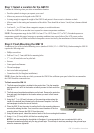
To ush mount the GMI 10:
1. Theush-mounttemplateisincludedintheproductbox.Trimthetemplate
andensurethatitwilltinthelocationatwhichyouwanttoushmountthe
GMI 10.
2. Theush-mounttemplatehasadhesiveontheback.Removetheprotective
linerandapplythetemplatetothelocationwhereyouwanttoushmount
the GMI 10.
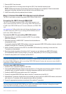
3. Using the 3
17
/
32
in. (90 mm) hole saw, cut the mounting surface along the
insideofthedashedlineindicatedontheush-mounttemplate.Useale
andsandpapertorenethesizeofthehole.
4. PlacetheGMI10intothecutouttoconrmthatthefourmounting-holesare
correctafterreningthehole.Ifnot,markthecorrectlocationsofthefour
mountingholes.RemovetheGMI10fromthecutout.
5. Usingthecenterpunch,indentthecenterofeachofthefourmounting-holelocations.
6. Using a
1
/
8
in.(3.2mm)drillbit,drillthefourmountingholes.
NOTE:Ifyouaremountingthechartplotterinberglass,itisrecommendedtouseacountersinkbittodrilla
clearance-counterborethroughonlythetopgel-coatlayer.Thiswillhelptoavoidanycrackinginthegel-coatlayer
when the screws are tightened.
•
•
•
•
•
•
•
•
•
•
•
•
•
•