


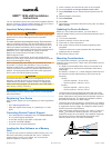
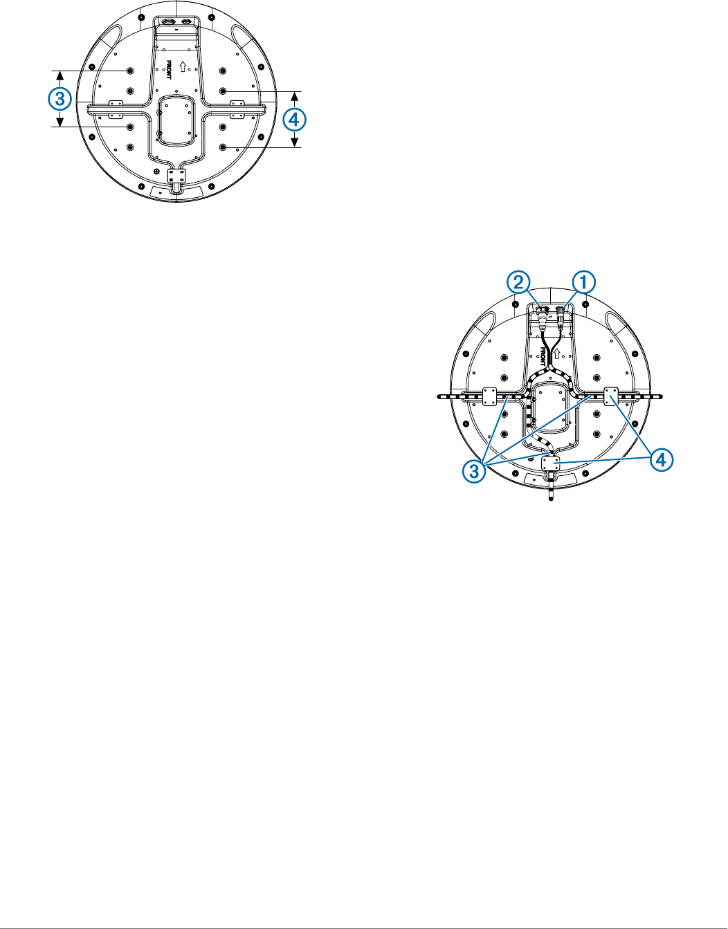
• The radome has two mounting options when installed on a
standard marine mount. One mounting option is closer to the
center of the radome
Â
, and the second option is offset
towards the back
Ã
to move the radar further away from the
mast.
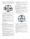
• The device should be mounted away from heat sources such
as smoke stacks and lights.
• The device should be mounted at a different level than
horizontal spreaders and mast crosstrees.
• To avoid interference with a magnetic compass, the device
should not be mounted closer to a compass than the
compass-safe distance value listed in the product
specifications.
• Other electronics and cables should be mounted more than
2 m (6 ½ ft.) from the radar beam path.
• GPS antennas should be either above or below the radar
beam path.
• The device should be mounted at least 1 m (40 in.) from any
transmitting equipment.
• The device should be mounted at least 1 m (40 in.) away
from cables carrying radio signals such as VHF radios,
cables, and antennas.
For Single Side Band (SSB) radios, increase the distance to
2 m (6 ½ ft.).
Cable Considerations
It may be necessary to drill 31.7 mm (1 ¼ in.) holes for routing
the power or network cable. The provided rubber cable
grommet can be used to cover a cable installation hole.
• The grommet does NOT provide a waterproof seal. To make
the grommet waterproof, marine sealant must be applied.
• Additional cable grommets can be purchased from Garmin or
a Garmin dealer.
When installing the power and network cables, you should
observe these considerations.
• Cutting the Garmin Marine Network cable is not
recommended, but a field install kit can be purchased from
Garmin or a Garmin dealer if cutting the network cable is
necessary.
• To ensure safety, appropriate tie-wraps, fasteners, and
sealant should be used to secure the cable along the route
and through any bulkheads or the deck.
• Cables should not be run near moving objects and high-heat
sources or through doorways and bilges.
• To avoid interference with other equipment, power and
network cables should not be run next to or parallel to other
cables, such as radio antenna lines or power cables. If this is
not possible, the cables should be shielded with metal
conduit or a form of EMI shielding.
• The power cable should be installed as close to the battery
source as possible.
◦ If is necessary to extend the power cable, the appropriate
gauge of wire must be used as directed in these
instructions.
◦ Incorrectly extended runs of cable may cause the radar to
malfunction due to insufficient power transmission.
Mounting the Radar
Before you mount the radar, you must review the mounting
location considerations and select a mounting location.
NOTE: The supplied M8 x 1.25 x 60 threaded rods can be used
on mounting thicknesses of 5 to 30 mm (
3
/
16
to 1
3
/
16
in.)
(recommended). For surfaces over 30 mm (1
3
/
16
in.), use
longer threaded rods.
1
If you are not installing the device on a pre-drilled Garmin-
compatible radar mount, use the included mounting template
to drill four 9.5 mm (
3
/
8
in.) mounting holes.
2
Install the locking ring and o-ring on the end of the Garmin
Marine Network cable.
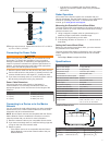
3
Connect the power cable to the power port
À
and the
network cable to the network port
Á
.
4
Press the cables into any of the guide grooves
Â
on the
bottom of the case, and secure them using a cable hold-
down plate
Ã
.
The cables should be bent or twisted as little as possible.
5
Position the radome on the mounting surface with the
triangular mark on the case aligned to the front of the vessel.
6
Apply the included anti-seize compound to the threads of the
four M8 x 1.25 x 60 threaded rods.
7
Insert the four threaded rods into the mounting holes on the
bottom of the radome.
Up to 50 mm (2 in.) of the threaded rods may extend below
the radome.
8
Apply a bead of marine sealant on the mounting surface
around each mounting hole.
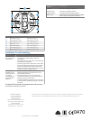
9
Fasten the radome
Ä
to the mounting surface
Å
using the
threaded rods
Æ
, flat washers
Ç
, spring washers
È
, and hex
nuts
É
.
2