


Garmin Radome Installation Instructions
3
Installation Procedures
The following order of mounting the radome and attaching the power and network cables may vary depending on the installation location and
mount used.
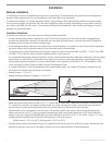
Mounting the Radome
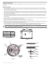
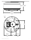
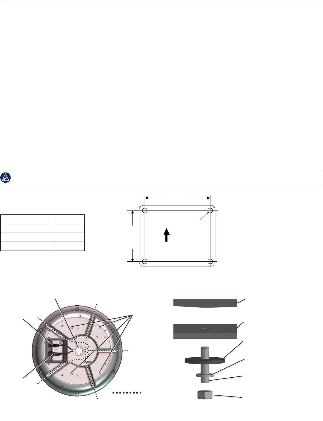
1. When a suitable mounting location is determined, verify that the mounting hole locations are aligned fore and aft, and use the included
mounting template or reference Figure 1 to drill four 9.5 mm (
3
/
8
") mounting holes. (This step is not necessary if you are using a pre-drilled
Garmin compatible or Raymarine
®
mount.)
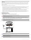
2. Align the notch and locking ring on the power cable to the power connector. Press the 2-pin power cable to the power connector and the RJ-
45 marine network cable to the RJ-45 socket (Figure 2). Turn the power cable locking ring clockwise until it stops. Tighten the RJ-45 locking
ring clockwise until it is rmly sealed.
3. The power and network cables may be pressed into any of the ve guide grooves molded into the bottom of the radome case and secured
under the cable hold-down plate (Figure 2). Avoid excessive bending or twisting of the cables. See the following “Cable Runs” section for
more information.
4. Position the radome on the mounting surface with the triangular mark on the case aligned to the front of the vessel. Apply a bead of marine
sealant around each of the mounting holes on the mounting surface.
5. Apply the included anti-seize compound to the threads of the four M8 x 1.25 x 60 threaded rods.
6. Install the four (4) M8 x 1.25 x 60 threaded rods into the mounting holes on the bottom of the radome. There should be no more than 50 mm
± 1mm (2") extruding from the radome when they are installed properly.
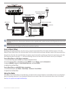
7. Fasten the radome to the mounting surface using the M8 x 1.25 x 60 threaded rods (installed in the previous step), spring washers, at
washers, and M8 Hex nuts as shown in Figure 3. The nuts should be torqued to between 13.7-18.6 N m (10-14 lb ft).
The supplied M8 x 1.25 x 60 threaded rods can be used on mounting thicknesses of 5-30 mm (
3
/
16
" - 1
3
/
16
") (recommended). For surfaces over
30 mm (1
3
/
16
"), locally supplied longer threaded rods are needed.
Wire Gauge Table
Figure 1
141.5 mm
(5 /
16
"
)
"
9.5 mm
(
3
/
8
"
)
"
233 mm
(9
5
/
32
"
)
"
Ship's Bow
2 meters (6
1
/
2
ft)
16 AWG
4 meters (13 ft) 14 AWG
6 meters (19 ft) 12 AWG
Figure 2
Mounting
holes
Power
connector
Network
connector
Cable routing
options
Plate
Mounting
bracket
Flat
washer
Spring
washer
M8 x 60
threaded
rod
Radome
M8 nut
Figure 3