


4
GMR 18/24 Marine Radar Installation Instructions
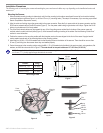
Cable Runs
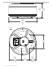
Route the cables as needed, depending on the type of mount you are using. It may be necessary to drill 31.7 mm (1.25") holes for routing the
power or network cable. Garmin provides a rubber cable grommet which may be used to cover a cable installation hole. The grommet does
NOT provide a waterproof seal. To waterproof the grommet, apply a marine sealant. Additional cable grommets can be purchased through
Garmin or a Garmin dealer.
When installing the power and network cables, observe the following:
It is not recommended to cut the RJ-45 marine network cable, but the GMR 18/24 package includes a eld install kit if it is necessary to
do so. Make sure you save the end you cut. It is important that the wires are connected to the new RJ-45 connector the same way.
To ensure safety, use the appropriate tie-wraps, fasteners, and sealant to secure the cable along a route and through any bulkhead or deck.
Avoid running the cables near moving objects, high-heat sources, or through doorways and bilges.
Avoid installing the cables next to or parallel to other cables, such as radio antenna lines or power cables. This is essential to avoid
interference to or from other equipment. If this is not possible, shield the cables with metal conduit or a form of EMI shielding.
Install the power cable as close to the battery source as possible. A minimum of 10.5 VDC is required during radar turn-on and operation.
Reference the wire gauge table on the previous page when using extended runs of wire between the power cable and the battery.
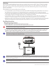
Final Wiring Connections
Making the nal wiring connections
1. Connect the Black ground (-) wire to the vessel’s negative power terminal.
2. Connect the Red power (+) wire (with fuse holder) to the vessel’s positive power terminal.
WARNING: Do not cut the fuse holder from the red wire. The fuse holder must remain in place for the GMR 18/24 to function correctly.
Removing the inline fuse holder may damage your boat's circuitry.
3. For a stand-alone network (chartplotter and radar only), attach the RJ-45 marine network cable to the RJ-45 socket on the back of the
chartplotter. For an expanded network (chartplotter, radar, GMS 10, etc.), attach the RJ-45 marine network cable to an open RJ-45
socket on the GMS 10 network port expander. Tighten the RJ-45 locking ring clockwise until it is rmly sealed.
NOTE: If you are using a Garmin GPSMAP 4000 or 5000 series chartplotter, you may not need a GMS 10 network port expander. The GPSMAP
4000 and 5000 series chartplotters have multiple RJ-45 sockets.
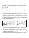
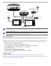
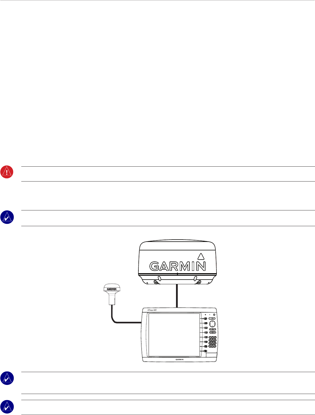
Stand-alone Network
GMR 18/24 marine radar
GPS 17
Garmin
Chartplotter
NOTE: When using the GMR 18/24 with a stand-alone network, the chartplotter and GPS antenna (GPS 17) must be installed according to their
installation instructions. This diagram only shows how a GMR 18/24 radar communicates with a stand-alone network and does not illustrate the full
wiring needs of the chartplotter or GPS 17.
NOTE: Both the GMR 18/24 and Garmin chartplotter must be connected to a power source according to their installation instructions. This
diagram only illustrates the network data connections.
•
•
•
•