


VHF 300 Series Installation Instructions 3
* A
1
/
8
in. (3 mm) pilot hole is nominal for plywood. Different dashboard materials my require a different size pilot hole.
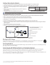
Connect the transceiver box to a 12 Vdc battery through an accessible switch.
Install the GHS 10 connected to station one on the transceiver box in the wheelhouse or an adjacent room per Federal Communications
Commission (FCC) law.
Ensure that you install each component of the VHF radio at least 20 in. (.5 m) from any compass. Test your compass to verify that it operates
correctly when the radio is operating.
Extension cables are available for the GHS 10 cable.
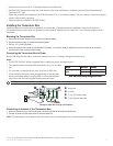
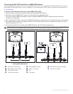
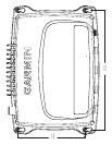
Installing the Transceiver Box
Install the transceiver box below deck on a bulkhead, in a location that is dry and protected from washdown. Ensure that the location is
well ventilated and away from objects that generate heat. Ensure that the transceiver box is at least 20 in. (.5 m) from any compass to avoid
interference.
Mounting the Transceiver Box
1. Ensure that the chosen location is dry, protected, and well-ventilated.
2. Use the template on page 11 to determine mounting holes.
3. Drill four
1
/
8
in. (3 mm) pilot holes.*
4. Mount the transceiver box using the included M4.2×25 screws. You can also use bolts, washers, and nuts (not included) to mount the
transceiver box if the mounting surface allows.
Connecting the Transceiver Box to Power
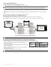
Use the VHF 300 power/data cable to connect the transceiver box to a 12 Vdc battery through an external switch.
Notes:
Use the VHF 300 Power Wiring-Assignment Table to identify the positive and negative wires.
The replacement fuse on the power/data wiring harness is a 10 A, slow-blow
fuse.
If it is necessary to extend the power wires, use at least 16 AWG wire.
If your boat has an electrical system, you might be able to wire the radio
directly to an unused holder on your fuse block. If you use the fuse block,
remove the in-line fuse holder supplied with the power/data cable.
NOTICE: Cover the connections with a waterproof, adhesive tape, such as rubber vulcanizing tape, to prevent water from seeping into the radio.
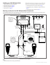
Wiring the VHF 300 Through a Fuse Block
➊
Boat ground
➋
10 A fuse
➌
To 10.8-15.6 Vdc boat supply
➍
To VHF 300 power/data cable
-
+
➋
+
–
➊
➌
➍
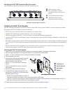
Connecting an Antenna to the Transceiver Box:
1. Mount the antenna on your boat according the instructions provided by the antenna manufacturer.
2. Connect the antenna to the antenna port on the transceiver box.
NOTE: The antenna port is on the opposite side of the transceiver box from the primary row of connectors pictured on page 4.
•
•
•
•
•
•
•
•
Device Wire Color Function
VHF 300 power/data
cable
Red Power—positive (+)
Black Ground—negative (-)
VHF 300 Power Wiring-Assignment Table
Device Wire Color Function
VHF 300 power/data
cable
Red Power—positive (+)
Black Ground—negative (-)
VHF 300 Power Wiring-Assignment Table