


9
307043
Air Motor Service
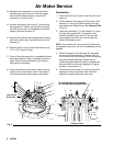
6. Install the toggle pins (Z) in the yoke (O). As-
semble the toggle assembly (U) by placing a well
greased spring onto the toggle arm (T) and then
the toggle rocker (S). Place the toggle arm (T)
ends of the toggle assembly (U) onto the toggle
pins, and snap the pivot pin (S) ends of the toggle
assembly into the lugs (P).
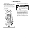
7. Set gap on inlet valve (N) using the .145 in. (3.68
mm) side of gauge 171818. Rotate valve stem (X*)
until snug against gauge, then back off until valve
stem slot is lined up with wire holes in valve nut
(J*) (do not back off more than 1/2 turn). See the
Cutaway View Fig. 3.
8. Tighten the bottom valve nuts (K*) securely by
hand.
9. Align the holes in the valve nuts (K*) and the slots
on the tops of the inlet valve poppets (N*), and
drop the lock wires (L*) through the holes in the
valve nuts and into the slots in the inlet valve
poppets. Pull the lock wires down tightly, and bend
the ends about 120_ with needle-pliers so that they
cannot be pulled back out of the holes.
CAUTION
Never re-use the old lock wires. They will get brittle
and break easily from too much bending.
Do not score the lock wires when you bend them
because they will break on the scoring.
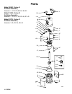
10. Grease and install the new o-rings on the piston
assembly (G) and in the groove in the air motor
base (F).
11. Clamp the air motor base (F) in a vise by closing
the vise jaws on the flange.
12. Grease and install the seal (2, 27 or 28) into the air
motor base (F). Install bearing (4) and ring retainer
(3) into the base for Model 206955. Grease and
install the bearing housing assembly (26 or 27) for
all other models.
13. Grease and install the bearing housing assembly
(26 or 27) for all Models except Model 206955, or
seal (2*), ring retainer (3) and bearing (4) for
Model 206955 into the air motor base (F).
14. Slide the piston rod (A) down through the bearing
housing assembly, and lower the piston assembly
(G) into the air motor base (F).
15. Carefully lower the cylinder (E) straight down onto
the piston assembly (G). Tighten the six screws
(D) holding the cylinder to the base (F).
CAUTION
To avoid damaging the cylinder wall, lower the cylin-
der straight down onto the piston. Never tilt the
cylinder as it is being lowered.
16. Grip the trip rod (C) with padded pliers. Remove
the 5/16 nut from the top of the trip rod. Screw the
cap nut (B) onto the trip rod (C), push the cap nut
down, and screw it into the top of the cylinder (E).
WARNING
MOVING PARTS HAZARD
Never operate the air motor with the air
motor identification plates removed. The
piston and associated parts can ampu-
tate a hand or finger caught between
them.
17. Replace the identification plates (19, 23 or 26)
before operating the air motor.
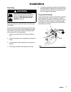
18. Before remounting the the air motor to the pump,
connect an air hose and run the air motor slowly,
starting with just enough air pressure to make the
air motor run, and make sure that it operates
smoothly.
19. Reconnect the ground wire before regular opera-
tion.