


4 308401
Service
Pressure Relief Procedure
WARNING
PRESSURIZED EQUIPMENT HAZARD
The system pressure must be manually relieved to
prevent the system from starting or spraying acci-
dentally. To reduce the risk of an injury from acci-
dental spray from the gun, splashing fluid, or
moving parts, follow the Pressure Relief Proce-
dure whenever you:
D are instructed to relieve the pressure,
D stop spraying,
D check or service any of the system equipment,
D or install or clean the spray nozzle.
1. Shut off the pump.
2. Open the dispensing valve, if used.
3. Open the fluid drain valve to relieve all fluid pres-
sure, having a container ready to catch the drain-
age.
Service
NOTE: Regular cleaning and inspection of the regula-
tor, based upon the degree and kind of service, is
essential.
1. Shut off the pump and open the back pressure
regulator by turning the adjusting screw (15)
counterclockwise until no spring pressure is felt.
Relieve all air and fluid pressures in the system.
2. Remove the back pressure regulator from the fluid
line.
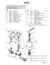
3. Disassemble the regulator and clean it with a
suitable solvent. See the parts drawing, page 5.
4. Carefully inspect the diaphragm (14) for cracks or
other damage. Replace if necessary.
5. Check for chips or dirt that could puncture the
diaphragm before assembling the regulator.
6. Reassemble the diaphragm and related parts.
Torque the cap nut (3) to 27 to 33 in-lb (3.1 to 3.7
NSm).
7. Carefully inspect the seat (1) for damage, wear, or
dirt. These things could cause the regulated pres-
sure to creep. Replace the seat if necessary.
8. Replace the seat gasket (6) when replacing the
seat (1). Torque the seat to 70 to 80 in-lb (8 to 9
NSm).
9. To remove or install the gauge on model 236770
(20), use the wrench on the square portion of the
gauge stud only.
CAUTION
Use thread sealer sparingly on the gauge’s male
threads when installing it to avoid plugging the
gauge.
10. Lubricate the adjusting screw (15) threads.
11. Assemble the remaining parts.
12. Tighten the regulator cap (4) to 324 to 396 in-lb (37
to 45 NSm).
13. Reinstall the back pressure regulator in the fluid
line.
Troubleshooting
WARNING
To reduce the risk of serious injury whenever you
are instructed to relieve pressure, always follow the
Pressure Relief Procedure above.
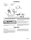
Checking the Ball and Seat
The ball and seat may be checked for wear by closing
the ball valve directly upstream of the back pressure
regulator (Fig 1). When the ball valve is closed, the
gauge pressure should drop slightly. If the pressure
continues to drop, then the ball or seat is worn and
needs to be replaced. Follow the preceding Service
procedure to replace the worn ball or seat.