


Overview
8 311593N
Overview
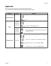
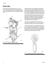
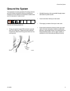
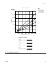
An electric motor (B) provides input to a 75:1 gear
reducer (GR), which drives two fluid pumps (FP). See
F
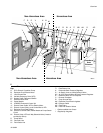
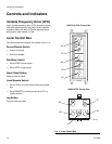
IG. 1. The stroke positions of the two pumps are offset
to achieve consistent flow from the pump assembly. See
F
IG. 2.
The optional sensor circuit includes a top dead center
(TDC) sensor which assists software in measuring
motor speed, and a pressure transducer (PT) with circuit
board, which measures fluid pressure at the pump out-
let. The Graco VFD software mimics the effect of a cam-
shaft, constantly adjusting motor speed to keep steady
fluid flow and achieve minimal pressure variation. The
output shaft of the gearbox and the connecting rods
experience the effect of the imaginary camshaft by
speeding up when the pressure drops (pump lower is at
a changeover) and slowing down when pressure
increases (both lowers are pumping).
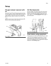
The VFD can be controlled by a local control box
mounted in the hazardous area, via communication pro-
tocol (such as modbus), or directly from the keypad.
F
IG. 3 shows a layout of a typical North American sys-
tem. The pump (A) may be controlled by a local control
box (C) mounted in the hazardous area, a variable fre-
quency drive (D) mounted in the non-hazardous area, or
remotely from a computer (Y). See manual 311592 for
pump and accessory installation information.
F
IG. 1. E-Flo Electric Circulation Pump
B
GR
PT
FP
FP
TDC (behind
cover)
ti8317c
FIG. 2. Cutaway Showing Offset Stroke Positions
ti8321a