Repair
12 312375J
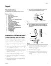
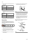
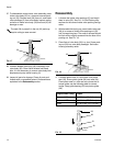
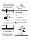
27. To disassemble intake check valve assembly, place
intake valve body (32) in a vise and unscrew pack-
ing nut (33). Remove seal (38) from nut, and intake
valve packings (S) from valve body. Inspect mating
surfaces of intake valve body (32) and seat (20) for
damage or wear.
28. Unscrew bleeder valve plug (40) completely from
valve body (39). Clean valve threads and bleed
hole. It is not necessary to remove valve body from
displacement pump outlet housing (2).
29. Inspect all parts for damage. Clean all parts and
threads with a compatible solvent. Reassemble as
explained in the Reassembly section.
Reassembly
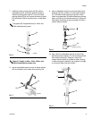
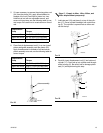
1. Lubricate the intake valve packings (S) and install
them in valve (32). See F
IG. 18. See Packing Kits
sections for the correct intake valve packing configu-
ration.
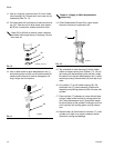
2. With beveled side facing up, press intake valve seal
(38) in to recess of intake valve packing nut (33)
until it snaps into place. The nose of the seal should
be flush with or slightly recessed into the face of the
packing nut. See F
IG. 18.
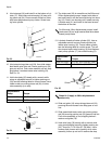
3. Place flats of valve body (32) in a vise. Screw pack-
ing nut (33) into valve body handtight. Set intake
housing assembly aside.
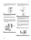
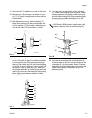
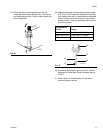
4. Lubricate piston seal (31) and install it on piston
seat (30). Screw piston guide (28) onto seat (30).
Place piston seat in a vise and use a brass rod to
torque guide; see the following table for correct
torque. Snap guide bearing (29) into piston guide
(28).
The seal (38) is press-fit in the nut (33) and may
require cutting to ease removal.
F
IG. 17
ti10572a
38
S
33
32
FIG. 18
Displacement Pump Torque
60cc and 100cc 26-30 ft-lbs (35-41 N•m)
200cc and 250cc 57-63 ft-lbs (77-85 N•m)
500cc 90-100 ft-lbs (122-135 N•m)
F
IG. 19
ti10572a
38
S
32
33
ti10573a
28
31
30
29


