TB 9-6625-1996-35
8
(10) Repeat (8) and (9) above as required to compensate for interaction.
(11) Disconnect oscilloscope and signal generator from TI, reinstall TI from panel,
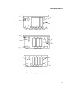
and reconnect CHAN A P1 cable to A9 J1 CH A and CHAN B P2 cable to A9 J2 CH B.
(12) Replace TI covers.
10. A12 Interface I/O
a. Performance Check
NOTE
This option can only be calibrated in an automated mode.
The TI must be connected to a controller with a properly
configured GPIB IEEE interface card.
NOTE
If you are running this section with any controller and or
software other than the fielded controller and the ICE
environment, you will have to write the required mnemonics
and take reading as per the software that you are using.
(1) Connect TI and multimeter IEEE connectors to the controller GPIB0.
(2) Assure TI address is set to 2 and multimeter address is set to 12.
(3) Adjust TI CHANNEL A and CHANNEL B LEVEL controls to PRESET.
(4) Remove screws holding TI top cover. Do not remove top cover until
instructed.
(5) Press the RESET key on the multimeter.
(6) Output the following mnemonic string to the TI: I2B500A500I1.
(7) Connect multimeter Input HI and LO to TI rear panel CHAN A
TRIG LEVEL.
(8) Output the following mnemonic string to the TI: B500A000I1.
(9) Retrieve the reading from the multimeter. If the reading is not
within limits listed in table 4, perform the listed adjustment.
(10) Repeat technique of (7) through (9) above for remaining table 4 entries.
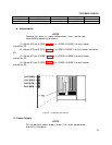
Table 4. A12 interface I/O.
Multimeter indication
Output
mnemonic
Connect multimeter to
test instrument
rear panel connector
Min
Max
Perform adjust
listed below
B500A000I1 CHAN A TRIG LEVEL -2.0005 -1.9995 b1


