


Flush Mount Temp/Speed Gauge
2
530501-1_B
5. Apply a generous amount of marine-grade silicone sealant inside the drilled hole and along the mating surfaces of the
threaded housing.
6. Insert the threaded housing through the drilled hole with the clevis pin holes oriented with the length of the boat.
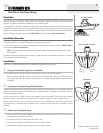
7. Slide the wing nut over the threaded housing, then Hand Tighten the wing nut ONLY until the assembly is firmly seated,
then tighten NO MORE than 1/8 of an additional turn. Make sure that the orientation of the clevis pin holes have not
changed.
CAUTION: To avoid damage, do not overtighten the wing nut. If the hull is wood, it will swell when wet.
NOTE: Remove the excess marine-grade silicone sealant from the outside of the hull to ensure smooth water flow over the
temp/speed gauge. Allow the sealant to dry according to the sealant manufacturer's recommendation before using your
boat. Then, check for leaks over the next 24 hours, and re-install the temp/speed gauge if necessary.
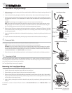
8. Slide two of the O-Rings over the gauge body and seat them into each groove. Lubricate the O-Rings and the inside
of the threaded housing. Orient the gauge so that the arrow on the flange points forward, and slide the gauge fully
into the threaded housing.
9. Insert the clevis pin through the holes in the threaded housing and gauge. Insert the ring clip through the hole on the
clevis pin.
10. Loop the chain around the cable coming from the gauge, and secure each end into the slots on the wing nut.
4. Routing the Cable
The temp/speed gauge cable must be routed to the point where the control head is mounted.
NOTE: Your boat may have a pre-existing wiring channel or conduit that you can use for the cable.
CAUTION! Do not cut or shorten the cable, and try not to damage the cable insulation. Route the cable as far as possible
from any VHF radio antenna cables or tachometer cables to reduce the possibility of interference. If the cable is too short,
extension cables are available to extend the cable up to a total of 50'. For assistance, contact the Customer Resource Center
at www.humminbird.com or call 1-800-633-1468 for more information.
1. Route and secure the cable, avoiding areas where it may be damaged or interfere with normal boating operations.
5. Connecting the Cable
Insert the temp/speed gauge cable into the appropriate terminal slot. The cable connectors are labeled, and there are
corresponding labels on the cable holder on the rear of the control head. The slots are keyed to prevent reversed installation,
so be careful not to force the connector into the holder.
Your Temp/Speed Gauge is now ready for operation.
Removing the Temp/Speed Gauge
Use the steps below to remove the Temp/Speed Gauge from your boat.
1. Carefully disconnect the temp/speed gauge cable from the control head.
2. Disassemble the temp/speed gauge and wing nut from the threaded housing.
3. Slide two of the O-Rings over the plug (included) and seat them into each groove of the plug body. Lubricate the O-
Rings and the inside of the threaded housing. Orient the plug so that the arrow on the flange points forward, and slide
the plug fully into the threaded housing.
4. Insert the clevis pin through the holes in the threaded housing and plug. Insert the ring clip through the hole in the
clevis pin.
For assistance, contact the Customer Resource Center at www.humminbird.com or call 1-800-633-1468 for more
information.
© 2008 Humminbird®, Eufaula AL, USA.
All rights reserved.
Securing the Wing Nut
Assembling the Gauge
Inserting the Pin and Ring Clip
Gauge
O-Ring
Clevis Pin Holes
Front of Boat
Wing Nut
Hull
(cut away view)
Threaded
Housing
Clevis Pin
Ring Clip