


Installing the HDR 200
Before mounting the HDR 200, gather the parts you need: HDR 200, mounting hardware
kit, and transducer cable. If the transducer cable is not long enough for your installation, see
“Accessories” earlier in this manula for information on the EC-6 10’ extension.
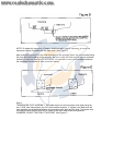
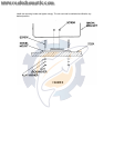
• The mounting surface should be adequately supported to protect the HDR 200 from
excess wave shock and vibration.
• The mounting area should allow at least 2” clearance at the back, sides, and top of the
unit for connection, air flow, and ease of removal.
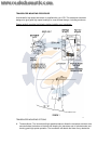
• Any VHF radio you have may incur some degree of interference with the depth sounder.
Humminbird depth sounders are designed to minimize this interference although it is best
to route the transducer cable and antenna cable as far away from each other as possible-
for example, on opposite sides of the boat.
After you have determined the best location for you HDR 200, proceed with the instructions on
the following page.
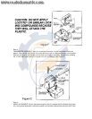
1. Locate an area on the dash or panel which is visible to the boat operator and free from
obstructions such as the throttle, steering mechanism or other gauges. The panel should
be sufficiently sturdy to protect the HDR 200 from excessive shock. The maximum
recommended panel thickness is ¾”, although thicker panels may be accommodated by
modifying the ‘U’ bracket.
2. Mark the desired location and drill a pilot hole.
3. Drill a 2-1/8” diameter hole using a hole saw and hand drill. Isnce this is a standard hole
size, hole saws are readily available for rental or purchase, or any marine service shop
can handle this task.
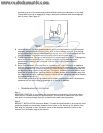
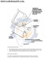
4. Insert the HDR 200 from the front of the panel.
5. From the rear of the panel, install the ‘U’ bracket and wingut as illustrated, ensuring the
face of the HDR200 is rotated upright.
6. If the panel into which you are mounting the unit is greater than ¼” thick, the ‘U’ bracket
at the score lines to reduce it’s length. It is a good idea to shorten the bracket gradually
(one tab at a time).
7. Tighten the wing nut to secure the installation.
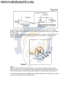
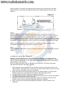
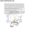
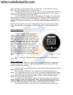
8. The power cable can be wired to any 12 VDC
power source, but wiring directly to the boat’s
fuse panel is most desirable. Connect the
black lead to the negative terminal and the
red lead to 12 VDC positive. Use a 1-amp
fuse in the fuse panel or if wiring directly to
the battery, use and in-line fuse holder with a
1 amp fuse. Do not connect the red lead to
the power source without a fuse. The
yellow lead turns the HDR 200 “on”. Connect
the yellow lead to a 12 VDC positive source
that only receives power when the boat’s
ignition is on. Connected in this fashion, the
HDR 200 will “power-up” whenever the boat’s
ignition is turned on. No fuse is necessary on the yellow lead. If your boat does not have
a switchable electrical system, you must wire the yellow lead through a separate switch,
then directly to the power source.
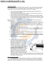
Section 3: Testing and Using
After installing your HDR 200, transducer, and cables, you should test the installation.
Testing should be performed in the water, since that is the only way to check your transducer’s
performance. When the boat ignition is turned on the HDR 200 will perform a self-test and then