


SECTION 3 DISASSEMBLY AND OPTION INSTRUCTIONS
3 - 1
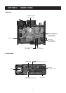
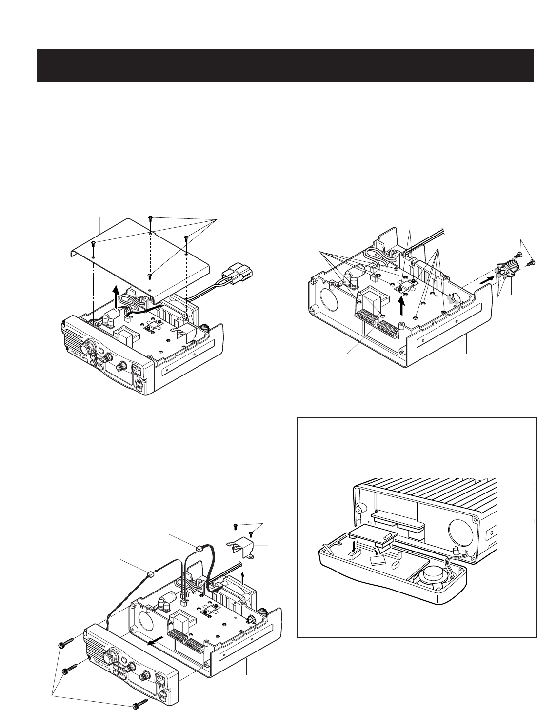
Cover
MP10
Front panel
Chassis
MP9
MP6
MP15
J5 (MF1)
J6 (SP7)
Chassis
Main unit
MP6
MP6
MP7
MP4
J1
A
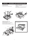
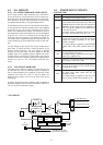
• REMOVING THE COVER
1 Unscrew 4 screws, MP10.
2 Remove the cover in the direction of the arrow.
• REMOVING THE FRONT PANEL
1 Unscrew 3 screws, MP9.
2 Unplug J6 to separate front panel and chassis.
3 Remove the front panel in the direction of the arrow.
4 Unplug J5 to separate fan and chassis.
5 Unscrew 2 screws, MP6, to separate MP15 and chassis.
• REMOVING THE MAIN UNIT
1 Unscrew 11 screws, MP6, and 2 screws, MP7, and 2
screws, MP4.
2 Unsolder 3 points, A, to remove the antenna connector.
3 Remove the Main unit in the direction of the arrow.
• OPTIONAL UNIT INSTALLATION
1 Install the optional unit as illustrated below. Insert it tight-
ly to avoid bad contact.