


PAGE2OF4
INSTALLATION
The 65053X-X Chop-Check Dispensing System comes completely
assembled. Remove unit from crate and place on a level surface.
Install material hose and dispensing device as required.
When the following instructions are observed, heavy paste materials
can be pumped directly from their original 5 gallon drum without air inĆ
clusion, or excessive waste. The follower plate creates an air tight seal
as well as clean-wiping action in its progressive downward movement
into the drum.
OPERATING INSTRUCTIONS
OPERATING INSTRUCTIONS / INITIAL SETUP PROCEDURE
WARNING STAND CLEAR. When raising or lowering the
lift.
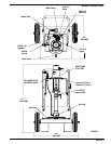
FOLLOWER PLATE
AIR SUPPLY VALVE
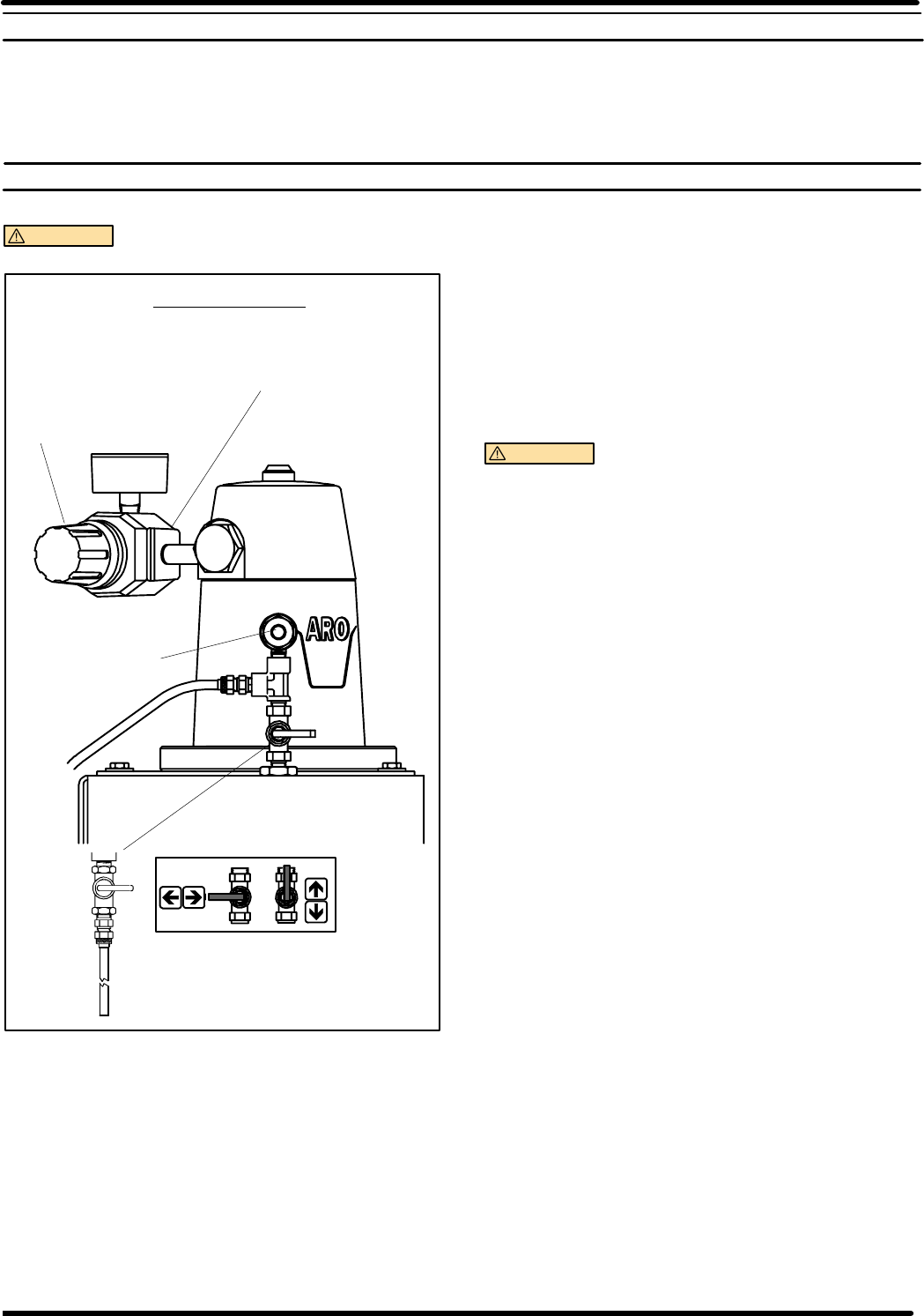
AIR CONTROLS
FIGURE 2
OFF
ON
2
PUMP AIR
REGULATOR
PUMP AIR
INLET
CART/LIFT
AIR INLET
TO RAISE LIFT, (THE FIRST TIME):
1. Take note of the pump/drum clearance above. Be certain the lift is
clear of any objects above the unit.
2. Adjust (Turn Needle Valve Knob Counter-Clockwise) air pressure to lift.
Connect the air supply (160 PSI MAX) to the air inlet.
3. Raise the lift high enough to clear the height of the drum. Stop the lift
upward travel by adjusting (Turn Needle Valve Clockwise until tight.)
Needle Valve.
REFER TO PAGE 3:
1. Once lift assembly and pump are in the ``UP" position, place and
center an opened 5 gallon drum of material on the lift base.Usethe
stops on the base to center 5 gallon drum. Tighten thumb screw to
secure drum.
2. Lubricate lower follower wiper plate seal with any typegrease.(siliĆ
cone, vaseline, gear, etc.) This ensures a smooth fit into the pail as
well as prevents curing type compounds from bonding to seal.
3. Check vent plug on follower plate to be sure it easily threads in and
out. It is recommended to lubricate the threads of the plug to help
prevent possible set up of compound at this point. See 65184X-X
Operator's Manual.
TO LOWER LIFT:
WARNING
PINCH HAZARD. Follower can descend quickly
causing injury. Keep hands clear when aligning with containĆ
er.
NOTE: Be certain the Follower Plate vent plug has been removed
so that the air trapped between the follower and the material is allowed
to escape from this vent. Captured air between the follower plate and
drum will escape.
NOTE: The lift may hesitate momentarily before starting downward,
the air pressure inside the post air chamber must decrease before it
will begin to descend.
1. Disconnect air line from the lift air inlet. Adjust (Turn Needle Valve Knob
Counter-Clockwise) Needle Valve to Lower the pump end into drum.
2. Replace the vent plug once the material begins to ooze from the
vent opening.
3. Adjust (Turn pump air regulator knob Counter-Clockwise to prevent
over pressurization of pump.) Knob on pump air regulator.
4. Connect air line to pump air regulator and adjust (Turn pump air reguĆ
lator Clockwise) air until pump begins to cycle.
5. Trigger gun to prime pump with material.
TO RAISE LIFT, (NORMAL OPERATION):
1. Disconnect air line from pump air regulator and connect to lift air
inlet. Adjust the Follower Plate Air Valve pressure up to approxiĆ
mately 8 psig. DO NO OVERPRESSURIZE THE DRUM to avoid
damage.
NOTE: Air from this valve will only pass when the unit is being
raised.
2. Adjust (Turn Needle Valve Knob Counter-Clockwise) air pressure on lift.
3. Raise the lift high enough to clear the height of the drum. Stop the
lift upward travel adjusting needle valve knob Counter-Clockwise.
TO CHANGE DRUM:
NOTE: The Needle Valve Knob should be turned Clockwise to hold lift
in the ``UP" Position.
1. Unsrew thumb screw and remove old 5 gallon drum.
2. Place and center. a new drum into position. Remove cover. TightĆ
en thumb screw.