


650875-X-B
PUMP
OPTION DESCRIPTION CHART
650875ā–āX
PACKINGMATERIAL
PLUNGERTYPE
SPRINGARRANGEMENT
(PACKINGS ARE UPPER AND LOWER UNLESS NOTED)
PACKING MATERIAL
P
UHMW-PE (LOWER)
SPRING ARRANGEMENT
3 NO SPRING
4 MULTIPLE WAVE SPRING
PLUNGER TYPE
4 CS W/HD CHROME PLATING
3 GLASS FILLED
C UHMW-PE
R
X
4
F UHMW-PE/LEATHER STAG'D (UPPER)
UHMW-PE (LOWER)
J POLYURETHENE (UPPER)
UHMW-PE (LOWER)
GENERAL
DESCRIPTION
WARNING HAZARDOUS PRESSURE. Do not exceed maxiĆ
mum operating pressureof 2250 psi(157 bar)at90 psi(6.3bar)
inlet air pressure.
PUMP RATIO X
INLET PRESSURETO PUMP MOTOR
=
MAXIMUMPUMP
FLUIDPRESSURE
Pump ratiois an expression of the relationshipbetween the pump motor area and
the lower pump end area. EXAMPLE: When 150 p.s.i. (10.3 bar) inlet pressure is
suppliedtothe motorofa 6:1ratio pumpitwill developamaximum of750 p.s.i.(52
bar) fluid pressure (at no flow) - as the fluid control is opened, the flow rate will
increase as the motor cycle rate increases to keep up with the demand.
WARNING Refer to general information sheet for additional
safety precautions and important information.
• The Extrusion (Chop-Check) pumps are primarily designed for the
pumping of heavy viscous materials with fiberous content. The
models can be used with a gravity feed single post lift as a topper
type assembly or with a two post lift as a force feed type assembly.
The lower pump is designed for easy priming and the double acting
feature is standard in all ARO industrial pumps. Material is delivĆ
ered to the pump discharge outlet on both the up and down stroke.
• The motor is connected to the lower pump end by a spacer section.
This allows for lubrication of the upper packing gland and prevents
motor contamination because of normal wear and eventual leakĆ
age through the material packing gland. Be sure the solvent cup is
adequately filled with lubricant to protect the upper packings and
insure longest service life.
TROUBLE SHOOTING
Pump problems can occur in either the Air Motor Section or the
Lower Pump End Section, use these basic guidelines to help deterĆ
mine which section is affected.
If the pump will not cycle.
• Be certain to first check for non-pump problems including kinked,
restrictive or plugged inlet/outlet hose or dispensing device. DeĆ
pressurize the pump system and clean out any obstructions in the
inlet/outlet material lines.
• Refer to the motor manual for trouble shooting if thepump does not
cycle and/or air leaks from the air motor.
If the pump cycles but does not deliver material.
• Refer to the lower pump end manual for further trouble shooting.
PUMP
CONNECTION – UPPER / LOWER
NOTE: All threads are right hand.
1. Lay the pump assembly on a workbench.
2. Remove the three nuts from the three spacer rods. (Fig. 1)
3. Pull the air motor from the lower pump end until motor piston rod is
in the ``down" position and lower pump end rod is in ``up" position.
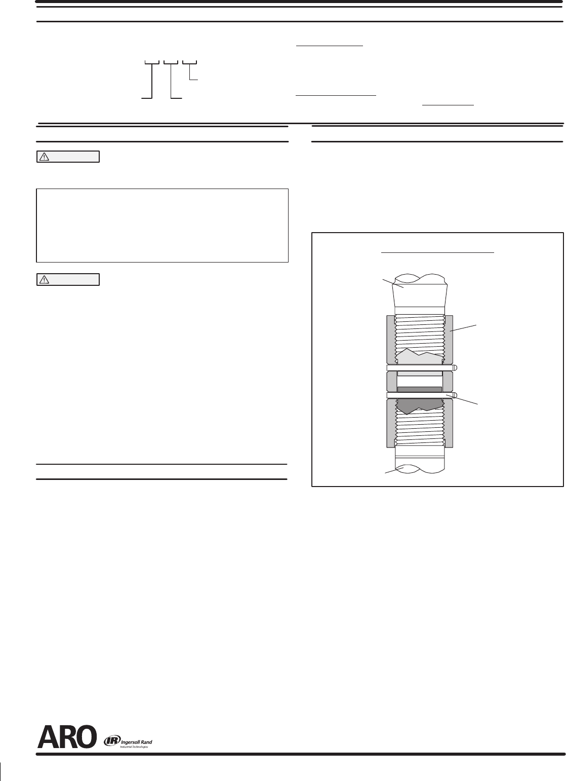
4. Remove the cotter pins and unthread piston rods from the connecĆ
tor. (Fig. 2)
Lower Pump
Piston Rod
Pump Motor
Piston Rod
CONNECTOR
92226
COTTER PIN
Y15–46–C (2)
PUMP CONNECTOR DETAIL
FIGURE 2
REASSEMBLY
1. Thread connector to pump motor piston rod until hole thru connecĆ
tor is aligned with hole thru piston rod.
2. Assemble cotter pin thru hole and bend ends of pin into groove of
connector.
3. Thread connector to lower pump piston rod until hole thru connecĆ
tor is aligned with hole thru piston rod.
4. Assemble cotter pin thru hole and bend ends of pin into groove of
connector.
5. Note: Heads and ends of cotter pins must not extend more than
.125" beyond o.d. of connector.
6. Reinstall the spacer rods to the pump motor.
7. Bring the motor and lower pump together and retain with the three
nuts.
PN 97999-491
15'&
PTFE
6).81&15'&45"(h%611&3
15'&
15'&6).81&45"(h%611&3
15'&-08&3