


650944-X-BPage 2 of 2
PUMP OPTION DESCRIPTION CHART
650944- X X X -B
PACKING MATERIAL
PLUNGER TYPE
SPRING ARRANGEMENT
PACKING MATERIAL (packings are upper and lower unless noted)
3
C UHMW-PE
G UHMW-PE / Leather staggered
P UHMW
R
SPRING ARRANGEMENT
4 Multiple wave spring with 316 stainless steel balls
7 Multiple wave spring with 440 stainless steel balls
PLUNGER TYPE
3 Hardened stainless steel with hard chrome plating
B Hardened stainless steel with ceramic coating
GENERAL DESCRIPTION
WARNING
HAZARDOUS PRESSURE. Do not exceed maxi-
mum operating pressure of 3960 p.s.i. (273.1 bar) at 1200 p.s.i.
(82.8 bar) inlet hydraulic pressure.
PUMP RATIO X MAXIMUM PUMP
INLET PRESSURE TO PUMP MOTOR
= FLUID PRESSURE
Pump ratio is an expression of the relationship between the pump motor area and the
lower pump end area. EXAMPLE: When 150 p.s.i. (10.3 bar) inlet pressure is supplied
to the motor of a 5:1 ratio pump it will develop a maximum of 750 p.s.i. (52 bar) fluid pres-
sure (at no flow) - as the fluid control is opened, the flow rate will increase as the motor
cycle rate increases to keep up with the demand.
WARNING
Refer to general information sheet for additional
safety precautions and important information.
• The two-ball pumps are primarily designed for the pumping of me-
dium viscosity fluids compatible with 300 series stainless steel. The
lower pump is designed for easy priming and the double acting fea-
ture is standard in all ARO industrial pumps. Material is delivered to
the pump discharge outlet on both the up and down stroke.
• The motor is connected to the lower pump end by a spacer section.
This allows for lubrication of the upper packing gland and prevents
motor contamination because of normal wear and eventual leakage
through the material packing gland. Be sure the solvent cup is ade-
quately filled with lubricant to protect the upper packings and insure
longest service life.
TROUBLE SHOOTING
Pump problems can occur in either the hydraulic motor section or the
lower pump end section, use these basic guidelines to help determine
which section is affected.
If the pump will not cycle.
• Be certain to first check for non-pump problems including kinked, re-
strictive or plugged inlet / outlet hose or dispensing device. Depres-
surize the pump system and clean out any obstructions in the inlet /
outlet material lines.
• Refer to the motor manual for trouble shooting if the pump does not
cycle and / or hydraulic fluid leaks from the hydraulic motor.
If the pump cycles but does not deliver material.
• Refer to the lower pump end manual for further trouble shooting.
PUMP CONNECTION - UPPER / LOWER
NOTE: All threads are right hand.
1. Lay the pump assembly on a workbench.
2. Remove the three screws and washers from the three spacer rods
(see figure 1).
3. Pull the hydraulic motor from the lower pump end until motor piston
rod is in the down" position and lower pump end rod is in up" posi-
tion.
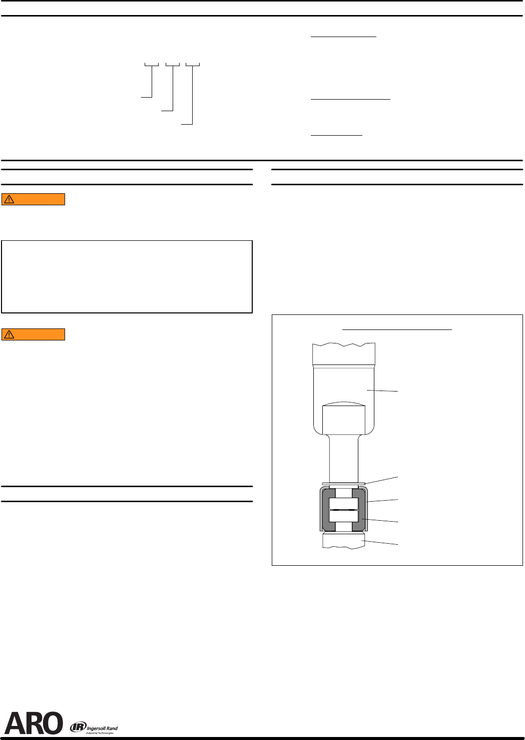
4. Using e-ring pliers, slide the retaining ring up far enough to allow the
sleeve to move upward and release the two connectors (see figure
2).
Lower Pump Piston Rod
Pump Motor Piston Rod
Retaining Ring 91547
Sleeve 91546
Connector 91644 (2)
PUMP CONNECTOR DETAIL
Figure 2
REASSEMBLY
1. Align the pump motor with the lower pump end.
2. Install the two connectors and retain with the sleeve, slide the retain-
ing ring back into position.
3. Reinstall the spacer rods to the pump motor.
4. Bring the motor and lower pump together and retain with the three
screws and washers.
PN 97999-740
Glass filled PTFE
-PE / PTFE staggered (upper) / UHMW-PE (lower)
PTFE / UHMW-PE staggered (upper) / PTFE (lower)