


Page 2 of 2 651511-X (en)
PN 97999-442
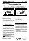
DISASSEMBLY / REASSEMBLY
If it becomes necessary to disassemble this unit, proceed in
the following manner:
Place gun in vise, holding at air cylinder head (13).
Unscrew screw assembly (2).
Unscrew cap (3).
Unscrew valve housing assembly (25).
The ball and socket assembly (23) will now be exposed.
By putting a wrench on the flats of the ball and socket
(23) and on the hex of the piston retainer (5), you can
unscrew the piston retainer (5).
Remove piston washer (6), piston (8) and piston washer (9).
Push piston rod forward (towards spray tip end of gun),
this will remove the piston rod (21), roll pin (22) and ball
and socket (23).
Unscrew retaining screw (10) from air cylinder head (13)
and check “O” ring (11).
Unscrew set screw (20) from spray gun body (19).
Unscrew spray gun body (19) from air cylinder head (13),
this will allow you to unscrew retainer (15) from spray
gun body (19) and inspect washer (16), packings (17)
and washer (18).
Reverse above procedure for assembly.
1.
2.
3.
4.
5.
6.
7.
8.
9.
10.
11.
PARTS LIST / 651511-X
Item Description
(size)
Qty Part No.
1 “O” Ring
(1/16” x 5/16” o.d.)
(1) Y325-8
2 Adjusting Screw
(includes item 1)
(1) 65958
3 Cap (1) 90995
4 “O” Ring
(3/32” x 2-5/16” o.d.)
(1) Y325-138
5 Piston Retainer (1) 90555
6 Piston Washer (1) 90586
7 Air Cylinder (1) 90556
8 Piston (1) 72842
9 Piston Washer (1) 90559
10 Retaining Screw (1) 90562
11 “O” Ring
(1/16” x 3/8” o.d.)
(1) Y325-10
12
“O” Ring
(3/32” x 2-1/16” o.d.)
(1)
Y325-134
13 Air Cylinder (1) 90994
14 Set Screw
(1/4” - 20 x 5/16”)
(1) Y29-43-C
15 Retainer (1) 79255
16 Washer (1) F174-9
17
Packing
(3)
90565
18 Washer (1) F15-64
19 Spray Gun Body (1) 92332
20 Screw
(#8 - 36 x 1/4”)
(1) Y191-82
21 Piston Rod (1) 90732
22 Roll Pin
(1/8” o.d. x 7/16”)
(1) Y178-36
23 Ball and Socket Assembly (1) 65774
24 Washer (1) 72851
25 Valve Seat Assembly (1) 65853
26 Washer (1) 75815
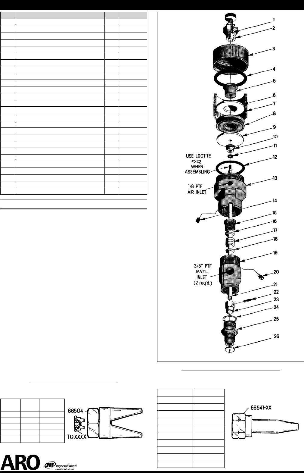
EXTRUSION - FOR MODEL 651511
Extrusion Nozzle and Retaining Nut Assembly. (Not included
and must be ordered separately)
TIP NO. ORIFICE DIA.
66541-03 0.031”
66541-04 0.046”
66541-06 0.063”
66541-09 0.093”
66541-12 0.125”
66541-15 0.156”
66541-17 0.172”
66541-18 0.187”
66541-25 0.250”
66541-37 0.375”
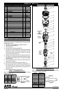
SPRAY - FOR MODEL 651511-1
Spray Tip (Must be ordered separately by customer. See tip
chart for desired size).
TIP NO. ORIFICE
PATTERN
WIDTH
TC-1850 0.018” 10”
TC-2140 0.021” 8.5”
TC-2150 0.021” 11.5”
TC-2640 0.026” 9”
TC-2650 0.026” 12”
Figure 3
Figure 4
Figure 5
Included but not shown
93140 wrench.