


PAGE 2 OF 4
INSTALLATION
FLUSH PUMP
1. Connect fluid hose to pump outlet and be sure all fittings are tight.
2. Turn air regulator knob counter--clockwise until it turns freely.
3. Pump hasbeentested inoil anda small amountremains forprotec-
tionagainstrusting.Immerselowerpumpendincompatiblesolvent.
4. Connect air hose coupler to connector on FRL.
5. Turn air regulator knob clockwise until air motor starts operating.
6. Flush pump with oil.
7. Disconnect air supply from air motor.
PUMP MODEL CHART
BASIC PUMP PUMP SPACER SECTION
*65875--C 65873 65874
*65875--1C 65873--1 65874
65875--2C 65873 65874--1 *
65875--3C 65873--1 65874--1 *
*65875--4C 65873--4 65874
65875--5C 65873--4 65874--1 *
(* OBSOLETE PUMPMODELS, SHOWN FOR REFERENCE ONLY)
* 65874- 1 uses a 92483-1 Tube in place of a 92483 Tube and a
90742-1 Rod Adapter in place of a 90742 Rod Adapter.
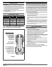
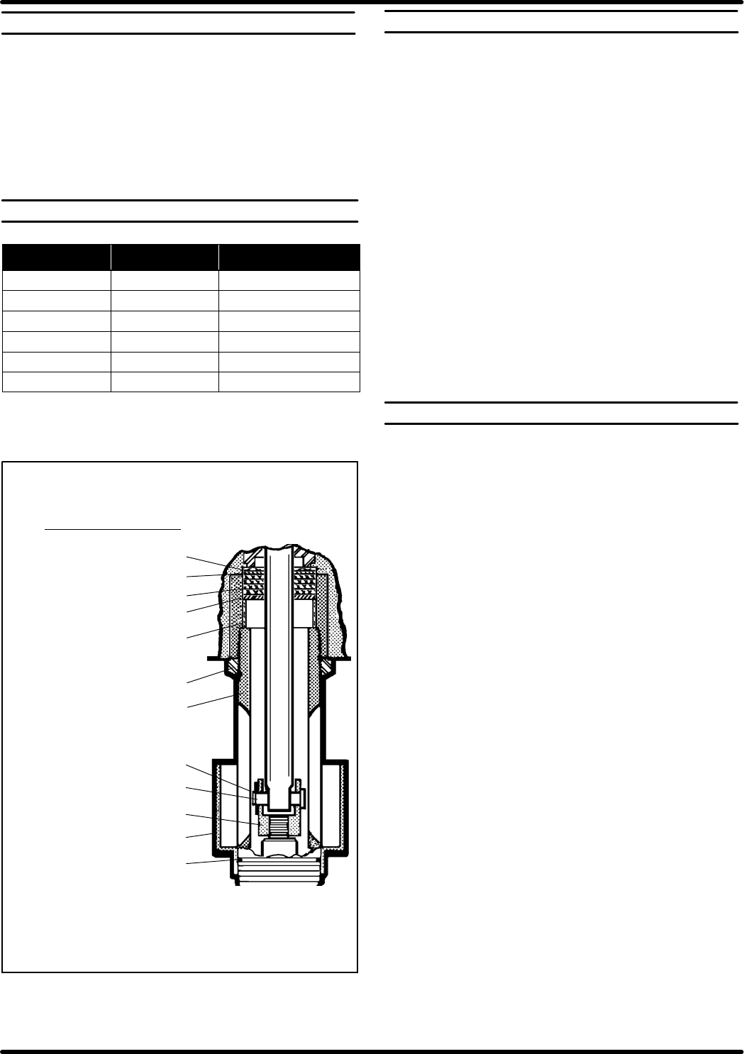
FIGURE 2
ADAPTER KIT 65874
90251 WAVY WASHER
90568 WASHER
90567 (4) PACKING
90568 WASHER
90570 SPACER
90571 LOCKNUT
92483 SPACER TUBE
Y145-2 RETAINING RING
90746 CONNECTING PIN
90742 ROD ADAPTER
Y325-32 ‘‘O” RING
91182 SOLVENT CUP
MAINTENANCE
Thebasic pumpconsistsoftwo m ajorcomponents:1. AirMotor,2. Low-
erPump.Themotorisconnectedtothelowerpumpendbyaspacersec-
tion. Thisallows for lubricationof the upper packinggland and prevents
motor contamination because of normal wear and eventual leakage
through thematerialpacking gland.Theair motoris removable andis to
be serviced separately. Refer to air motor manual for service andparts.
Itis recommendedthatanoiler be installedin theairline as closeas pos-
sibletothe pump.Thisincreases theservice lifeof thepumpbyreducing
wear of the air motor’s internal parts.
• Periodically flush entirepump system witha solvent that iscompat-
ible with the material being pumped.
• Pump disassembly should be done on a clean work bench with
clean cloths to keep parts clean.
• If replacement parts are necessary, consult drawing containing
parts for identification, include the part name andnumber when or-
dering.
• Before assembling, lubricate parts where required. When assem-
bling‘‘O”ringsorparts adjacentto ‘‘O”rings,caremust beexercised
to prevent damage to ‘‘O” rings and ‘‘O” ring groove surfaces.
• Ifpump isto beinoperative foran unspecifiedperiodoftime, discon-
nect air and relieve all pressure.
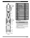
PUMP DISASSEMBLY
NOTE: All threads are right hand.
1. Clamp pump assembly in a vise on the air motor base assembly.
2. Unscrew 90571 Lock Nut. (See Figure 2)
3. Place a strap wrench around 92483 tube and loosen by turning
counterclockwise. If the wrench slips on t he tube, wrap a piece of
400 grit sand paper around tube and under strap wrench.
Note: Pipe wrench will damage the finish of the tube.
4. Afterthetubehasbeenpulleddowntoexposetheairmotorrod,hold
air motor piston rod and remove the Y145--2 retaining ring and
90746 pin from the air motor piston rod.
5. Remove the air motor assembly from the vise.
6. Visethe lowerpump andpush (6) pistonrod untilflats on(16) rodar
exposed at other end of pump.
7. Unscrew (20) stop nut and remove (19) washer and (18) washer
from (16) rod.
8. Unscrew (17) primer tube from (7) tube and sleeve and remove (9)
washer,(10)retaining ring, (11)‘‘U” cup,(12)body,(13) sleeve,(14)
gasket and (15) valve seat.
9. Hold (6) piston rod and unscrew (16) rod from assembly.
10. Push (6) rod until (8)connector is exposed on otherend of (7)tube.
11. Unscrew and remove (8) connector from (6) rod.
-‘‘Smart Parts”
K
eep these items on hand in addition to the Service
K
its
f
or
f
ast repair and reduction o
f
down time.