


Page 4 of 4 6694X-XXX (en)
PN 97999-12
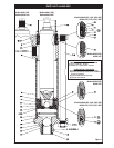
Install (50) female washer, upper packings, (53) male
washer and (44) wave spring in (1) solvent cup. NOTE:
The wave spring is split and the wave where the split oc-
curs should be next to the metal back-up washer.
Install (45) washer in (6) pump body and screw (1) sol-
vent cup into (6) pump body (do not tighten).
Put (8) “O” ring on (6) pump body.
Apply lubricant to (26) plunger and upper packing. Care-
fully slide the above assembled parts, (1) solvent cup and
(6) pump body with internal packing arrangement over
the top of (26) plunger. Retain (6) pump body in bench
vise and tighten (1) solvent cup (ARO tool 637406 is
available to tighten solvent cup). Carefully lay assembled
parts aside for future assembly.
Put lower packing on (36) seat body.
Install (40) retaining ring on (36) seat body and lay aside
for future assembly.
Put other (8) “O” ring onto (15) foot valve body.
Place (20) pin, (17) ball, (23) gasket and (22) ball seat
(bevel up) into (15) foot valve body and screw in (24)
seat retainer.
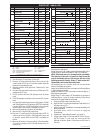
Position the (20) pin in the (15) foot valve body as described
in the following paragraph.
A. Bottom holes (closest to ball) should be used for
light viscosity materials.
B. Center holes for medium viscosity materials (as as-
sembled from factory).
C. Top holes for heavy viscosity materials.
NOTE: These assembled parts are to be laid aside for future
assembly.
9. Place assembled (26) plunger, (6) pump body and (1) sol-
vent cup, with packing upright, in a bench vise, retained
by the ats on (26) plunger at (1) solvent cup end. NOTE:
Plunger to be vertical in vise.
10. Put (27) ball in ball guide end of (26) plunger. Place (29)
gasket on sealing surface above ball guide. Apply Loctite
242 to threads of (26) plunger. Place (28) ball seat (bevel
up) into (36) seat body and assemble to (26) plunger.
NOTE: Tighten (36) seat body to 100 - 110 ft lbs (135.6
- 149.1 Nm). NOTE: ARO tool 637404-B is available to as-
semble body and plunger.
11. Lip on (72) wiper is to be rolled inward using a at sur-
face with no sharp edges (such as a steel dowel rod) to
prevent damage of packing plus easier assembly. This
process may have to be repeated several times to assure
1.
2.
3.
4.
5.
6.
7.
8
.
small enough diameter has been achieved to insure
proper assembly.
12. Apply lubricant to inside of (9) suction tube and carefully
slide over the assembled (71) packing and (72) wiper and
onto the (6) pump body.
NOTE: Once the suction tube has cleared (71) packing and
(72) wiper, a rubber mallet can be used to drive (9) suction
tube into place.
13. Apply lubricant to (8) “O” ring and assemble to (15) foot
valve body, then assemble (15) foot valve body into (9)
suction tube. A rubber mallet can be used in this applica-
tion.
14. Align the three holes in (15) foot valve body with the
three threaded holes in (6) pump body. Screw (10) tie
rods into (6) pump body. NOTE: Rods are to be ush with
the top side of (6) pump body. Using the ats provided
on (10) tie rod, secure the entire assembly with (12) nuts.
NOTE: Tighten (12) nuts to 60 - 70 ft lbs (81.3 - 94.9 Nm).
NOTE: Do not tighten each nut completely at once but
draw them equally together and then tighten.
TROUBLE SHOOTING
No material at outlet (pump continually cycles).
Check material supply. Disconnect or shut o the air sup-
ply and replenish the material. Reconnect.
Material on one stroke only (fast downstroke).
The (17) lower ball may not be seating in the (22) seat
(see lower pump disassembly). Remove the ball from the
seat, clean and inspect the ball and seat area. If the ball or
seat is damaged, replace.
Material on one stroke only (fast upstroke).
Check for worn or damaged packings and seals. Replace
the packings and seals as necessary.
Material leakage out of the solvent cup or material ap-
pears on the pump plunger rod.
Relieve the pressure in the pump and tighten the solvent
cup until leakage discontinues. If this procedure does not
aid in stopping the leakage problem, the upper packings
may be worn (see lower pump disassembly). Replace the
packings as necessary.
y
y
y
y