


Page 4 of 8 670106 (en)
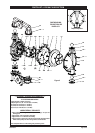
PARTS LIST / 670106 FLUID SECTION
637303-TA uid section service kits include: Balls (item 22), diaphragms (item 7) plus items 19, 70, 144, 175 (listed below) plus
174 and 94276 Lubriplate® FML-2 grease (page 6).
MATERIAL CODE
[A] = Aluminum
[B] = Nitrile
[C] = Carbon Steel
[Co] = Copper
[Sp] = Santoprene
[SS] = Stainless Steel
[T] = PTFE
PARTS LIST
Item Description
(size)
Qty Part No. [Mtl]
1 Rod (1) 94984 [C]
5 Backup Washer (2) 66167 [SS]
6 Diaphragm Screw (2) 94094 [SS]
7 Diaphragm (2) 94091-A [Sp]
15 Fluid Cap (2) 94107 [SS]
19 “O” Ring
(3/16” x 5” o.d.)
(4) Y328-350 [T]
21 Seat (4) 94113 [SS]
22 Ball
(3-1/4” diameter)
(4) 94103-T [T]
26 Screw
(M12 x 1.75 - 6g x 45 mm)
(12) 94412-2 [SS]
27 Screw
(M12 x 1.75 - 6g x 60 mm)
(16) 94991 [SS]
29 Nut
(M12 x 1.75 - 6h)
(16) 95053 [SS]
Item Description
(size)
Qty Part No. [Mtl]
32 Leg (2) 94703-2 [SS]
43 Ground Lug
(see page 7)
(1) 93004 [Co]
60 Inlet Manifold (1) 96785 [SS]
61 Outlet Manifold (1) 96784 [SS]
68 Air Cap (1) 94030-1 [A]
69 Air Cap (1) 94030-2 [A]
9
70 Gasket (2) 94100 [B]
131 Screw
(M10 x 1.5 - 6g x 120 mm)
(4) 94531 [C]
9
144 “U” Cup
(3/16” x 1-3/8” o.d.)
(2) Y186-51 [B]
9
175 “O” Ring
(3/32” x 1” o.d.)
(2) Y325-117 [B]
9
180 Gasket
(0.406” i.d. x 0.031” thick)
(4) 94098 [Co]
9
Indicates items included in 637421 air section repair kit.
FLUID SECTION DISASSEMBLY
Remove top manifold(s).
Remove (22) balls, (19) “O” rings and (21) seats.
Remove (15) uid caps.
Remove (6) diaphragm screws, (7) diaphragms and (5)
backup washers.
NOTE: Do not scratch or mar the surface of (1) diaphragm
rod.
1.
2.
3.
4.
FLUID SECTION REASSEMBLY
SERVICE NOTE: ARO pn 94094-TIL diaphragm assembly tool
is recommended for use when reassembling the pump.
Reassemble in reverse order.
Clean and inspect all parts. Replace worn or damaged
parts with new parts as required.
Lubricate (1) diaphragm rod and (144) “U” cup with Lubri-
plate FML-2 grease. (94276 grease packet is included in
service kit.)
Be certain the diaphragm assembly bottoms out on the
(1) rod.
Re-check torque settings after pump has been re-started
and run a while.
y
y
y
y
y
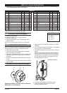
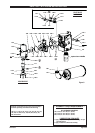
ASSEMBLING DIAPHRAGM ASSEMBLY
6
7
5
3
Diaphragm assembly: (3) Thread, (5) Back-up Washer, (6)
Diaphragm Screw, (7) Diaphragm.
Apply Loctite 271 Threadlocker to thread (3) on (5) Back-
up Washer.
Insert (7) Diaphragm insuring seal bead on (7) Diaphragm
is in the groove on (5) Back-up Washer.
Thread (6) Diaphragm Screw onto the stud on (5) Back-up
Washer.
Applying a light coating of Lubriplate FML-2 Grease to
the surfaces of (6) Diaphragm Screw and (7) Diaphragm,
being careful not to get grease on the Loctite prepared
area. This will reduce friction during tightening of the
assembly. Tighten 65-70 Ft-Lbs.
1.
2.
3.
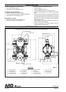
Diaphragm Assembly
1
Screw the two Diaphragm Assemblies to (1) Rod.
Tighten Diaphragm Assemblies to 65-70 Ft-Lbs.
Be sure to torque both sides.
1.
2.