


DISASSEMBLY
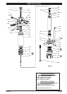
All threads are right hand. Refer to gure 2, page 3. These
procedures are for the installation of repair kit parts.
Disconnect power supply and relieve all system pressure
prior to servicing. Carefully remove the parts, inspect parts
for damage, nicks or excessive wear and determine if any
parts will need replacement.
Remove (1) top plug and remove (2) “O” ring.
Remove (8) trip plug and remove (5) ball, (38) spring fol-
lower, (6) spring and (7) “O” ring.
Move piston rod to the fully retracted position and pull
(4a) spool out of (4b) sleeve through the top.
Using the ats on (18) trip rod to hold, remove and dis-
card (3a) nut. DO NOT RE-USE. The trip rod wrench ats
are only accessible through the port holes that retain the
(8) trip plug. This will require a narrow width open-end
wrench.
NOTE: Be very careful when removing the spool from
the valve. The nish of this part is critical for proper
motor performance. Any nicks, scratches or dirt may
damage the set.
5. Remove (43) cap screws.
6. Slide (31) seal retainer, (29) bushing and (30) wiper off
(22) piston rod and (25) piston rod adapter.
7. Remove (37) tie rod nus and (35) washers.
8. Clamp (9) cylinder head and remove (26) motor base by
tapping with a soft hammer, then remove (10) “O” ring
and (28) polypack rod seal.
9. Remove (34) hydraulic tube from (9) cylinder head and
remove (32) “O” rings and (33) back-up rings.
10. Remove (22) piston rod assembly and (23) cylinder from
(9) cylinder head and remove (10) “O” ring.
11. Separate (22, 17, 21, 16, 15, 14) piston rod assembly from
(23) cylinder.
12. Remove (17) seal and (16) wear ring from (15) piston.
13. If further disassembly is required, such as removal of (22)
piston rod, (4) valve spool assembly, or (45, 20, 19, 18)
shifter assembly, see next section. (Order “O” rings sepa-
rately.)
Removal of (4) sleeve and spool assembly.
14. Remove (12) retaining ring and (11) sleeve washer from
(9) cylinder head. Push the (4b) sleeve carefully down
through the (9) cylinder head using a soft faced tool.
NOTE: The finish of the upper face of the sleeve is
critical for intended operation. Any nicks or scratches
may damage the entire (4) set.
Removal of (22) piston rod.
15. Place the (22, 21, 17, 16, 15, 14) piston rod assembly in
a vertical position with the (25) piston rod adapter in a
heavy vise.
NOTE: Never clamp on the (22) piston rod.
16. Grip the ats on the (14) piston screw and unthread.
17. Remove (21) “O” ring from (22) piston rod.
18. Remove the (18, 19, 20, 45) trip rod assembly.
19. Using the ats on the (18) rod, remove and discard the
two (3b) nuts. DO NOT RE-USE.
1.
2.
3.
4
.
REASSEMBLY
Thoroughly clean and lubricate all seals. Replace all soft
parts with new ones included in the repair kit.
Install (28) rod seal and (10) “O” ring into (26) motor base.
Install (30) wiper into (31) seal retainer and slip in (29)
bushing.
Slide (25, 22) piston rod assembly into (26) motor base
and retainer assembly from step #2 above.
Insert (21) “O” ring onto (22) piston rod and place (15)
piston on it.
Assemble (45) retaining ring, (19) trip washer, (20) trip
spring and (19) trip washer to (18) trip rod, securing with
one (3b) nut. NOTE: Orient the two (3b) nuts such that
the anges are facing each other. NOTE: (3b) nut to be
hand tight. While holding (18) trip rod on ats, assemble
(3b) nut to (18) trip rod and tighten to 90 - 110 in. lbs
(10.2 - 12.4 Nm).
Place (18, 19, 20, 45, 3b) shifter assembly into (22) piston
rod and thread (14) piston screw into (22) piston rod.
Torque (14) piston screw to 100 - 120 ft lbs (135.6 - 162.7
Nm) with (25) piston rod adapter in a heavy vise.
Put (17) seal and (16) wear ring on (15) piston.
Push (22) piston rod to fully extended position and place
(23) cylinder over the piston assembly.
Seat the (23) cylinder onto the motor base. NOTE: Petro-
leum jelly is recommended for ease of assembly on all “O”
rings and inside the cylinder.
Replace the three (13) “O” rings on (4b) valve sleeve.
Push (4b) valve sleeve / spool set straight into (9) cylin-
der head.
Place (11) sleeve washer behind (4b) valve sleeve and
retain this with (12) retaining ring.
Put two (33) back-up rings and two (32) “O” rings onto
(34) hydraulic tube with back-up rings on the hydraulic
tube rst.
Push tube assembly (34, 33, 32) into (26) motor base.
Place (10) “O” ring on (9) cylinder head, lower (9) cylinder
head onto the (23) cylinder and (34) hydraulic tube with
the (18) trip rod through the center of the valve.
Feed (36) bolts through (26) motor base and apply (35)
washers and (37) nuts to the bolts. Tighten fasteners al-
ternately and apply 44 - 56 ft lbs (59.7 - 75.9 Nm). NOTE:
Must alternately rundown fasteners to prevent cutting
the (10) “O” rings.
Assemble (31) seal retainer, retaining with six (43) cap
screws.
Move piston to the retracted position.
Pull (18) trip rod through the head and place the (4a)
spool on the trip rod. Using the (3a) nut and the trip rod
flats, tighten the (3a) nut to 90 - 110 in. lbs (10.2 - 12.4
Nm).
Carefully push the spool / trip rod into the sleeve, creat-
ing the (4) valve.
Place (2) “O” ring on (1) top plug and tighten in (9) cylin-
der head.
Place (7) “O” ring on (8) trip plug. Place (5) ball in (9) cyl-
inder head and (6) spring and (38) spring follower in (8)
trip plug.
Thread the (8) trip plug into the (9) cylinder head.
1.
2.
3.
4.
5.
6.
7.
8.
9.
10.
11.
12.
13.
14.
15.
16.
17.
18.
19.
20.
21.
22.
23.
24.
Page 4 of 4 67314-B (en)
PN 97999-1220