


PART NUMBER FOR ORDERING
t
1
2
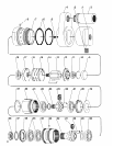
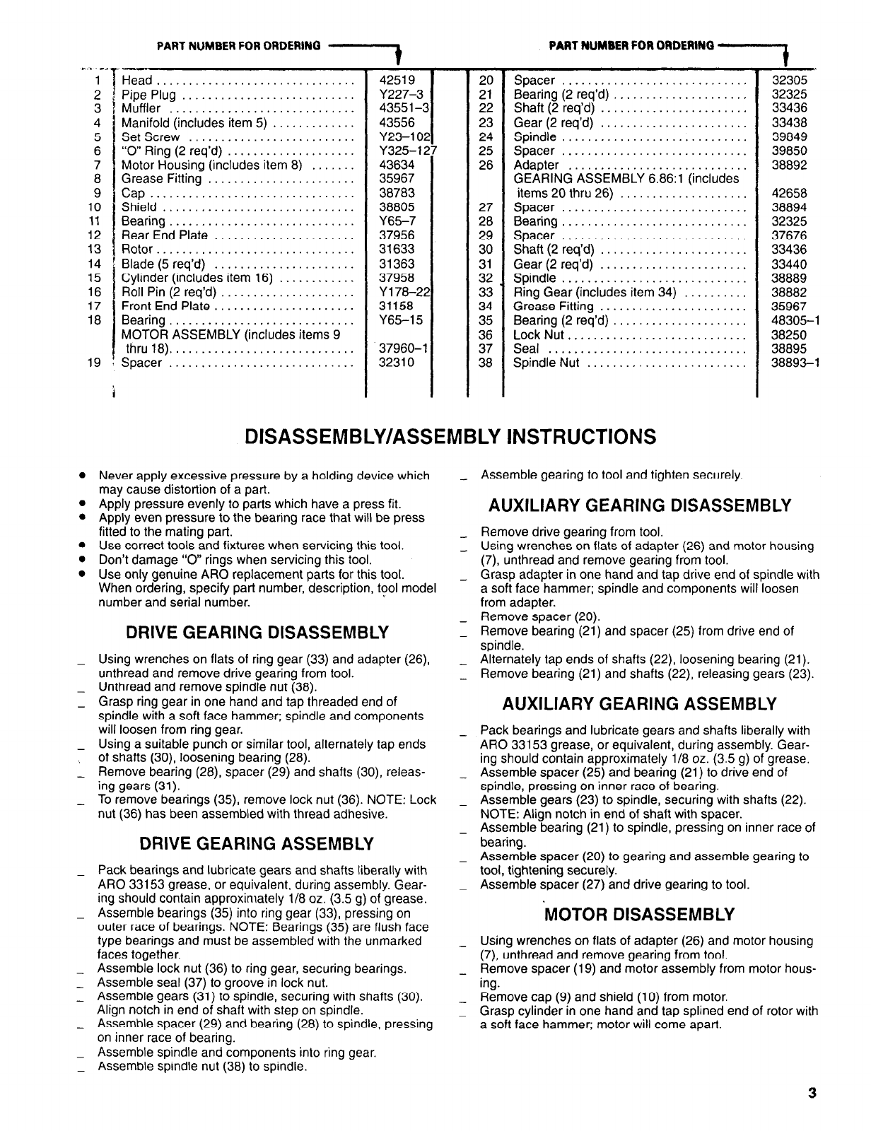
Head ...............................
Pipe Plug
3 Muffler
...........................
.............................
4 Manifold (includes item 5) .............
5
Set Screw ..........................
6 “0” Ring (2 req’d) ....................
7 Motor Housing (includes item 8) .......
8 Grease Fitting .......................
9 Cap.. ..............................
10
Shield ..............................
11
Bearing .............................
12 Rear End Plate ......................
13 Rotor ...............................
14 Blade (5 req’d)
15
16
......................
Cylinder (includes item 16) ............
Roll Pin (2 req’d) .....................
17 Front End Plate ......................
18
Bearing .............................
MOTOR ASSEMBLY (includes items 9
thru 18) .............................
19 Spacer .............................
.
42519
Y227-3
43551-c
43556
Y23-102
Y325-127
43634
35967
38783
38805
Y65-7
37956
31633
31363
37958
Y178-22
31158
Y65-15
37960-l
32310
20
21
22
23
24
25
26
27
28
29
30
31
32
33
34
35
36
37
38
Spacer .............................
Bearing (2 req’d) .....................
Shaft (2 req’d) .......................
Gear (2 req’d) .......................
Spindle .............................
Spacer .............................
Adapter ............................
GEARING ASSEMBLY 6.86:l (includes
items 20 thru 26) ....................
Spacer .............................
Bearing.. ...........................
Spacer .............................
Shaft (2 req’d) .......................
Gear (2 req’d) .......................
Spindle .............................
Ring Gear (includes item 34) ..........
Grease Fitting .......................
Bearing (2 req’d) .....................
Lock Nut ............................
Seal ...............................
Spindle Nut .........................
DISASSEMBLY/ASSEMBLY INSTRUCTIONS
l
Never apply excessive pressure by a holding device which
may cause distortion of a part.
l
Apply pressure evenly to parts which have a press fit.
l
Apply even pressure to the bearing race that will be press
fitted to the mating part.
l
Use correct tools and fixtures when servicing this tool.
l
Don’t damage “0” rings when servicing this tool.
l
Use only genuine ARO replacement parts for this tool.
When ordering, specify part number, description, tool model
number and serial number.
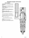
DRIVE GEARING DISASSEMBLY
-
Using wrenches on flats of ring gear (33) and adapter (26),
unthread and remove drive gearing from tool.
-
Unthread and remove spindle nut (38).
-
Grasp ring gear in one hand and tap threaded end of
spindle with a soft face hammer; spindle and components
will loosen from ring gear.
-
Using a suitable punch or similar tool, alternately tap ends
., of shafts (30), loosening bearing (28).
-
Remove bearing (28), spacer (29) and shafts (30), releas-
ing gears (31).
-
To remove bearings (35), remove lock nut (36). NOTE: Lock
nut (36) has been assembled with thread adhesive.
DRIVE GEARING ASSEMBLY
-
Pack bearings and lubricate gears and shafts liberally with
ARO 33153 grease, or equivalent, during assembly. Gear-
ing should contain approximately 1/8 oz. (3.5 g) of grease.
-
Assemble bearings (35) into ring gear (33), pressing on
outer race of bearings. NOTE: Bearings (35) are flush face
type bearings and must be assembled with the unmarked
faces together.
-
Assemble lock nut (36) to ring gear, securing bearings.
-
Assemble seal (37) to groove in lock nut.
-
Assemble gears (31) to spindle, securing with shafts (30).
Align notch in end of shaft with step on spindle.
-
Assemble spacer (29) and bearing (28) to spindle, pressing
on inner race of bearing.
-
Assemble spindle and components into ring gear.
-
Assemble spindle nut (38) to spindle.
-
-
-
-
-
-
-
-
-
-
-
-
-
t
32305
32325
33436
33438
39849
39850
38892
42658
38894
32325
37676
33436
33440
38889
38882
35967
48305-I
38250
38895
38893-l
Assemble gearing to tool and tighten securely.
AUXILIARY GEARING DISASSEMBLY
Remove drive gearing from tool.
Using wrenches on flats of adapter (26) and motor housing
(7), unthread and remove gearing from tool.
Grasp adapter in one hand and tap drive end of spindle with
a soft face hammer; spindle and components will loosen
from adapter.
Remove spacer (20).
Remove bearing (21) and spacer (25) from drive end of
spindle.
Alternately tap ends of shafts (22), loosening bearing (21).
Remove bearing (21) and shafts (22), releasing gears (23).
AUXILIARY GEARING ASSEMBLY
Pack bearings and lubricate gears and shafts liberally with
ARO 33153 grease, or equivalent, during assembly. Gear-
ing should contain approximately 1/8 oz. (3.5 g) of grease.
Assemble spacer (25) and bearing (21) to drive end of
spindle, pressing on inner race of bearing.
Assemble gears (23) to spindle, securing with shafts (22).
NOTE: Align notch in end of shaft with spacer.
Assemble bearing (21) to spindle, pressing on inner race of
bearing.
Assemble spacer (20) to gearing and assemble gearing to
tool, tightening securely.
Assemble spacer (27) and drive gearing to tool.
MOTOR DISASSEMBLY
Using wrenches on flats of adapter (26) and motor housing
(7), unthread and remove gearing from tool.
Remove spacer (19) and motor assembly from motor hous-
ing.
Remove cap (9) and shield (10) from motor.
Grasp cylinder in one hand and tap splined end of rotor with
a soft face hammer; motor will come apart.
3