


AF044X-XX & AF046X-XX (en) Page 3 of 8
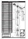
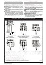
PARTS LIST / AF044X-XX & AF046X-XX
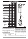
AIR MOTOR MODEL NO.
AF0441-XX
AF0442-XX
AF0443-XX
AF0444-XX
AF0445-XX
AF0460-XX
Item Description
(size)
Part No. (Qty) [Mtl]
101
Base & Bearing
(Stub)
** 65020 (1) [A]
Base & Bearing 65023 (1) [A]
Base & Bearing
(Stub)
65775 (1) [A]
Base
(Stub)
90074 (1) [A]
102
O-Ring
(1/8” x 1” O.D.)
Y325-210
(1)
[B]
O-Ring
(1/8” x 1 5/8” O.D.)
Y325-220 (1) [B]
103
Bushing 93310 (1) [D]
104
Retainer 93311 (1) [SS]
105
Guide 93312 (1) [SS]
106
Plate 93958 (1) [A]
107 Lock Washer Y14-616-C (4) [C]
108
Screw
Y6-66-C
(4)
[C]
109
Nut
(1/2” - 20)
Y11-8-C (4) [C]
110
Plug
(1/2-14 N.P.T. X 9/16”)
93897-1 (1) [PP]
112
Cylinder
96936 (1) [Ef]
96935 (1) [Ef]
114
Tube
96874-1 (1) [C]
96874-2 (1) [C]
121
Bolt
(1/2” - 20 x 10 1/4”)
94046-1 (4) [C]
Bolt
(1/2” - 20 x 8 1/4”)
94046-2 (4) [C]
151
Washer 90103 (1) [A]
152
U-Cup
(1/4” X 1 1/4” O.D.)
Y186-16 (1) [B]
153
Washer 73986 (1) [Br]
154
Snap Ring
(1.456” O.D.)
Y147-131 (1) [C]
*203
Piston Assembly
(includes items 115, 117, 118,
119, & 120)
67489 (1) --
67490 (1) --
67491 (1) --
67492 (1) --
67493 (1) --
67494 (1) --
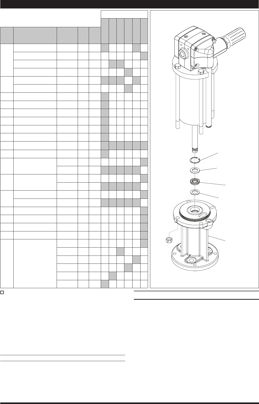
101
151
152
153
154
�
Figure 3
Indicates where parts are used.
Items included in Service Kit (637489).
NOTE: Base styles and lower packings may vary from that
shown on the cover. Refer to model number in the chart
above.
For simplication of ordering and stocking, the Universal Ser-
vice Kit contains service parts that can be used for every size
of air motor. When repairing the motor, use only the parts that
are needed for that specic motor. Extra service parts from the
kit will remain after repair of the air motor.
MATERIAL CODE
[A] = Aluminum [D] = Acetal
[B] = Buna Nitrile [PP] = Polypropylene
[Br] = Brass [SS] = Stainless Steel
[Bz] = Bronze [Ef] = Epoxy - Fiberglass Filament Reinforced
[C] = Carbon Steel
[CK] = Ceramic
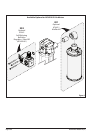
DISASSEMBLY OF AIR MOTOR
NOTE: All threads are right hand.
Force the piston assembly up by pushing the (115) rod
toward the top of the air motor.
Remove the (155) muffler/(201) muffler assembly for
ease of disassembly.
Remove four (138) socket head screws from the (140)
head manifold. Remove the (140) head manifold by
pulling up and outward to remove from tubes (114) and
(137).
Remove (141) major gasket from the (140) head mani-
fold.
Remove tubes (114) and (137) by pulling upward.
Remove the four (113) O-rings from both tubes (114) and
(137).
1.
2.
3.
4.
5.
6.
(continued on page 4)