


Page 4 of 4 AF1060-XX (en)
PN 97999-1473
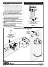
Loosely install the (114) tube into the bore in the (101)
base assembly.
Install the (141) manifold gasket into the (140) mani-
fold and telescope onto both (114 & 137) tubes until
the (113) O-rings are seated. Fasten the (140) manifold
to the (144) valve block using four (138) socket head
screws. Install one (139) socket head screw thru the ear
of the (140) manifold into the (122) head plate. Tighten
all ve (138 & 139) fasteners to torque specications.
Install the (155) muer/(201) muer assembly.
28.
29.
30.
REASSEMBLY OF AIR MOTOR (CONT’D)
TROUBLE SHOOTING
Air leakage out of main exhaust.
Damaged (141) track gasket. Replace (141) track gasket.
Worn (116) piston seal. Replace (116) piston seal.
Continual air leakage out (149) pilot exhaust.
Worn (136) “U” cup. Damaged (148) track gasket. Replace
(136) “U” cup and (148) track gasket.
Air leakage out (149) pilot exhaust only during the down
stroke.
Worn (133) “U” cup. Rolled or damaged (128) “O” ring. Re-
place (133) “U” cup and (128) “O” ring.
Air leakage around (115) piston rod.
Worn or damaged (152) “U” cup. Replace (152) “U” cup.
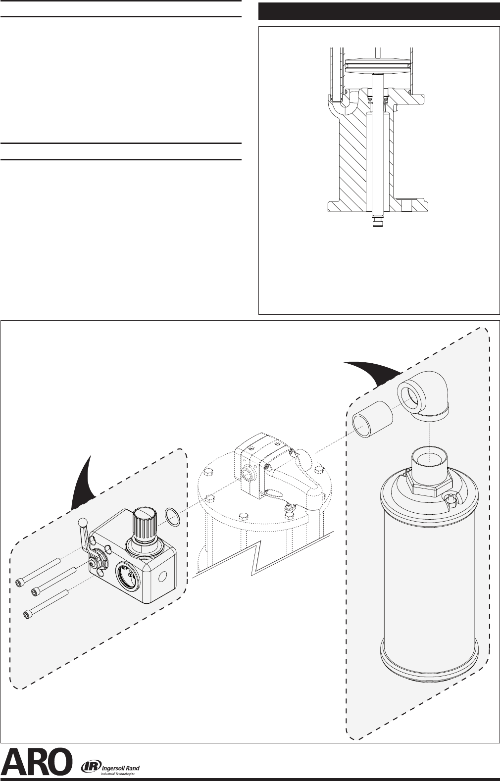
Available Options for AF1060-XX Air Motors
201
Optional
67445-4
Muer Kit
202
Optional
67442
Self-Relieving
Ball Valve
Regulator / Shut-O
(AF1060-01)
Figure 4
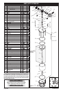
TYPE -0-
Divorced Base, Quick Coupled Rod
65023 BASE and
67489 PISTON ASSEMBLY
Air Motor Base and Rod Combination
Figure 3